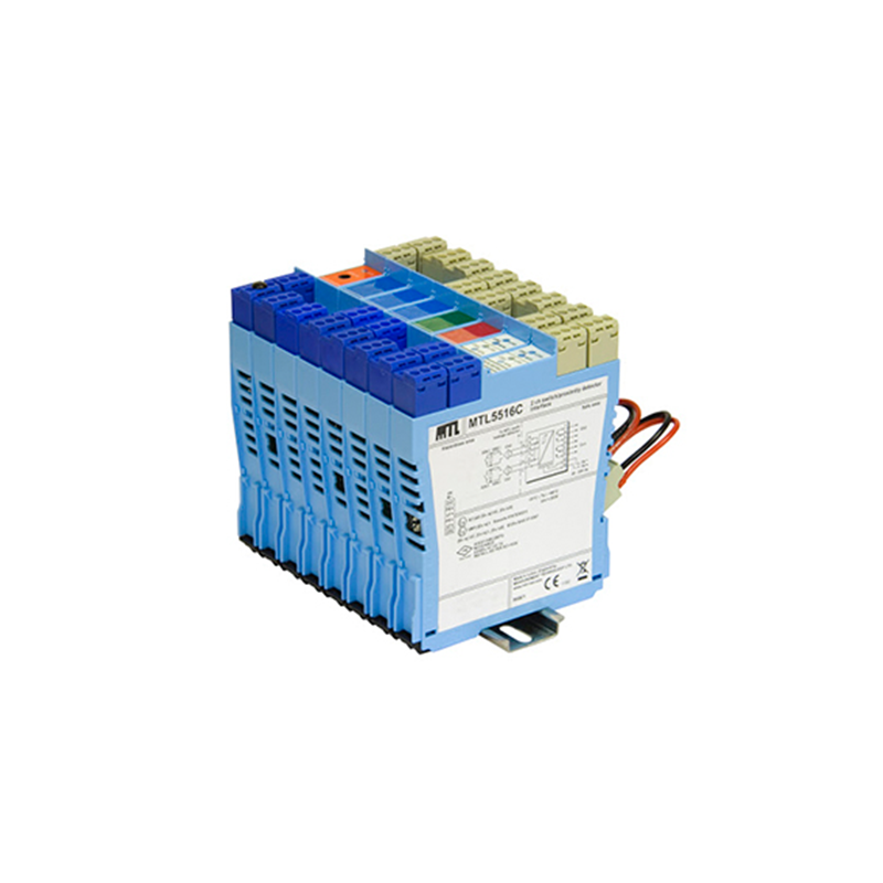
Separator 2-Kanal MTL4513-MTL5513
  • Separator 2-Kanal MTL4513-MTL5513

Fotos dienen nur zu Informationszwecken.

please use latin characters

Hersteller: MTL Instruments

Separator 2-Kanal MTL4513-MTL5513

The MTLx513 enables two solid-state outputs in the safe area to be controlled by two switches or proximity detectors located in the hazardous area. The Ch1/Ch2 output transistors share a common terminal and can switch +ve or -ve polarity signals. Independent output phase reversal and line fault detection are enabled via switches for each output. LFD indication is provided on the top of the module.

Specification


Number of channels Two
Location of switches Zone 0, IIC, T6 hazardous area
Div 1, Group A hazardous location
Location of proximity detector Zone 0, IIC, T4–6 hazardous area, if suitably certified
Div.1, Group A, hazardous location
Hazardous-area inputs Inputs conforming to BS EN60947–5–6:2001 standards for proximity detectors (NAMUR)
Voltage applied to sensor 7 to 9V dc from 1kΩ ±10%
Input/output characteristics Normal phase:
• Outputs closed if input > 2.1mA (< 2kΩ in input circuit)
• Outputs open if input < 1.2mA (> 10kΩ in input circuit)
Hysteresis: 200μA (650Ω) nominal
Line fault detection (LFD) (when selected)* User-selectable via switches on the side of the unit
Open-circuit alarm on if Iin < 50 uA
Open-circuit alarm off if Iin > 250 uA
Short-circuit alarm on if Rin < 100 Ohm
Short-circuit alarm off if Rin > 360 Ohm
Safe-area output Floating solid-state outputs compatible with logic circuits
Operating frequency: dc to 500Hz
Max. off-state voltage: ± 35V
Max. off-state leakage current: ± 50µA
Max. on-state resistance: 25Ω
Max. on-state current: ± 50mA
LED indicators Green: power indication
Yellow: four: on when output active
Red: LFD indication + faulty channel’s yellow LED flashes
Maximum current consumption 30mA at 24V
Power dissipation within unit 0.65W typical at 24V, with 10mA loads
0.78W max. with 50mA loads
Safety description (each channel) Uo=10.5V Io=14mA Po=37mW Um = 253V rms or dc

(*) Resistors must be fitted when using the LFD facility with a contact input:
500 Ohm to 1kΩ in series with switch
20 kOhm to 25kΩ in parallel with switch
(**) Note: reactive loads must be adequately suppressed.

Relay characteristics


 MTL4513MTL5513
Response time 10ms maximum 10ms maximum
Contact rating (Safe Area) 10W, 0.5A, 35V dc 250V ac, 2A, cosØ >0.7, 40V dc, 2A, resistive load
Contact rating (Zone 2) 10W, 0.5A, 35V DC 35V, 2A, 100VA.


SIL capable


These models have been assessed for use in IEC 61508 functional safety applications. SIL2 capable for a single device (HFT=0) SIL3 capable for multiple devices in safety redundant configurations (HFT=1)

See data on MTL web site and refer to the safety manual.


MTL4513


MTL5513 


Senden Sie eine Anfrage

Interessieren Sie sich für dieses Produkt? Benötigen Sie zusätzliche Informationen oder individuelle Preise?

Kontaktiere uns
FRAGEN SIE NACH DEM PRODUKT close
Vielen Dank für die Zusendung Ihrer Nachricht. Wir werden so schnell wie möglich antworten.
FRAGEN SIE NACH DEM PRODUKT close
Durchsuche

Zur Wunschliste hinzufügen

Sie müssen eingeloggt sein

The MTLx513 enables two solid-state outputs in the safe area to be controlled by two switches or proximity detectors located in the hazardous area. The Ch1/Ch2 output transistors share a common terminal and can switch +ve or -ve polarity signals. Independent output phase reversal and line fault detection are enabled via switches for each output. LFD indication is provided on the top of the module.

Specification


Number of channels Two
Location of switches Zone 0, IIC, T6 hazardous area
Div 1, Group A hazardous location
Location of proximity detector Zone 0, IIC, T4–6 hazardous area, if suitably certified
Div.1, Group A, hazardous location
Hazardous-area inputs Inputs conforming to BS EN60947–5–6:2001 standards for proximity detectors (NAMUR)
Voltage applied to sensor 7 to 9V dc from 1kΩ ±10%
Input/output characteristics Normal phase:
• Outputs closed if input > 2.1mA (< 2kΩ in input circuit)
• Outputs open if input < 1.2mA (> 10kΩ in input circuit)
Hysteresis: 200μA (650Ω) nominal
Line fault detection (LFD) (when selected)* User-selectable via switches on the side of the unit
Open-circuit alarm on if Iin < 50 uA
Open-circuit alarm off if Iin > 250 uA
Short-circuit alarm on if Rin < 100 Ohm
Short-circuit alarm off if Rin > 360 Ohm
Safe-area output Floating solid-state outputs compatible with logic circuits
Operating frequency: dc to 500Hz
Max. off-state voltage: ± 35V
Max. off-state leakage current: ± 50µA
Max. on-state resistance: 25Ω
Max. on-state current: ± 50mA
LED indicators Green: power indication
Yellow: four: on when output active
Red: LFD indication + faulty channel’s yellow LED flashes
Maximum current consumption 30mA at 24V
Power dissipation within unit 0.65W typical at 24V, with 10mA loads
0.78W max. with 50mA loads
Safety description (each channel) Uo=10.5V Io=14mA Po=37mW Um = 253V rms or dc

(*) Resistors must be fitted when using the LFD facility with a contact input:
500 Ohm to 1kΩ in series with switch
20 kOhm to 25kΩ in parallel with switch
(**) Note: reactive loads must be adequately suppressed.

Relay characteristics


 MTL4513MTL5513
Response time 10ms maximum 10ms maximum
Contact rating (Safe Area) 10W, 0.5A, 35V dc 250V ac, 2A, cosØ >0.7, 40V dc, 2A, resistive load
Contact rating (Zone 2) 10W, 0.5A, 35V DC 35V, 2A, 100VA.


SIL capable


These models have been assessed for use in IEC 61508 functional safety applications. SIL2 capable for a single device (HFT=0) SIL3 capable for multiple devices in safety redundant configurations (HFT=1)

See data on MTL web site and refer to the safety manual.


MTL4513


MTL5513 


Kommentare (0)