
Sie müssen eingeloggt sein
Category


Fotos dienen nur zu Informationszwecken.
please use latin characters
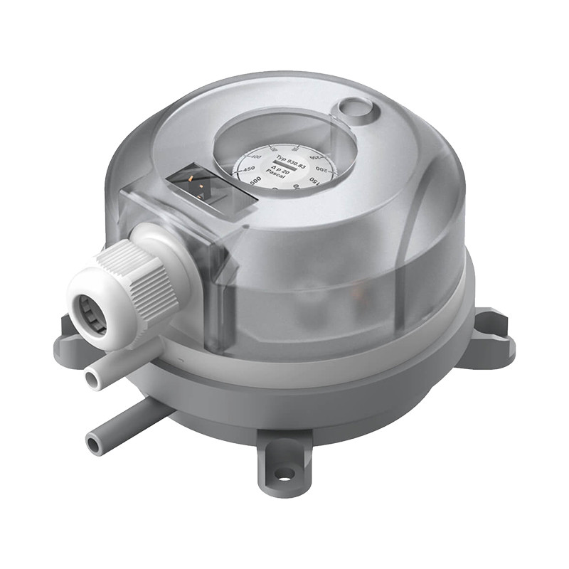
With adjustable switching pressure for Ex zones 1 and 2
Applications
Adjustable differential pressure switch for monitoring overpressure, vacuum and differential pressure of air or other non-aggressive, combustible gases.
Possible fields of application include:
Technical Specifications:
| Medium | air, (non-)combustible and non-aggressive gases |
| Temperature ranges: | |
| Medium and ambient temperature | -20˚C do +85 ˚C |
| Storage temperature | -40˚C do +85 ˚C |
| Switching pressure ranges | 20-200Pa (minimum) |
| 1,000-4,000 (maximum) | |
| Switching differential | 10 Pa minimum |
| 250 Pa maximum (depending on pressure range) | |
| Switching pressure tolerance | ±15% from setpoint |
| Max. working overpressure | 10kPa |
| Pressure connections | 2 plastic hose ports |
| Outer diameter | 6mm |
| Materials: | |
| Diaphragm | silicone, tempered at 200° C, free of gas emissions (other materials on request). |
| Pressure switch housing | PA 6.6 |
| Cover | PS |
| Weight | 150/110 g (with/without cover) |
| Electrical rating | 24 VDC/100 mA; 30 VDC/45 mA |
| Electrical connections | AMP flat plug, 6.3 mm x 0.8 mm, in accordance with DIN 46244 or push-on screw terminals |
| Cable conduit | PG-11 or M20 x1.5 with cable strain relief |
| Protection category | IP 54 (with cover) |
| Mechanical working life | over 106 switching operations |
ATEX
| EC type examination | BVS 06 ATEX E 141X |
| Device category | II 2G |
| Ignition protection type | II B T4 |
| CE conformity | ATEX Directive 94/9/EG |
| RoHS-Directive 2002/95/EG |
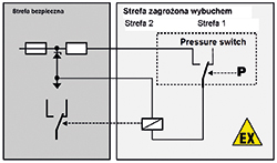
This pressure switch can be used in potentially explosive zones 1 and 2. In the safe area, an associated isolating means (separating barrier, switching amplifier) must be connected before. The entire isolating circuit must then be proved to keep inherent safety.
For this purpose, the power specifications (P, I, U) of the barrier must be lower and the characteristics (L, C) higher than those of the pressure switch and of the connection line (blue colour).
Characteristics for IIB:
Voltage- Ui 24VDC/30VDC
Current-Ii 100mA/45mA
Capacitance -Ci 0μF
Inductance -Li 0mH
| Switching pressure setting range [Pa] |
Switching differential set to |
Tolerance for max. and min. switching pressure |
930,8 | EX | ||||||||
|---|---|---|---|---|---|---|---|---|---|---|---|---|
| from | to | |||||||||||
| 20 | 200 | 10 | ±15% | 0 | ||||||||
| 30 | 400 | 15 | ±15% | 4 | ||||||||
| 50 | 500 | 20 | ±15% | 3 | ||||||||
| 200 | 1,000 | 100 | ±15% | 5 | ||||||||
| 500 | 2,500 | 150 | ±15% | 6 | ||||||||
| 1,000 | 4,000 | 250 | ±15% | 7 | ||||||||
| Electrical connection using 6.3 x 0.8 mm flat plug | 1 | |||||||||||
| Electrical connection using enclosed screw terminals | 4 | |||||||||||
| Fitting method using fastening eyes | 2 | |||||||||||
| Scale in mbar | 1 | |||||||||||
| Scale in Pasca | 2 | |||||||||||
| Scale in Pascal and inWC | 3 | |||||||||||
| IP 54 with cable conduit PG-11 | 1 | |||||||||||
| IP 54 with cable conduit M20 x1.5 | 2 | |||||||||||
| Packaging | bulk packed, 45 pcs. per carton | 1 | ||||||||||
| bulk packed, folding boxes included | 2 | |||||||||||
| individually boxed | 3 | |||||||||||
| Accessories | without accessories | 1 | ||||||||||
| with S-shaped metal mounting bracket 6402 | 2 | |||||||||||
| with L-shaped metal mounting bracket 6401 | 3 | |||||||||||
| with Climaset ® 6555 | 4 | |||||||||||
| with Climaset ® 6550 | 5 | |||||||||||
| with metal mounting bracket 6402 and Climaset ® 6555 | 6 | |||||||||||
| with metal mounting bracket 6402 and Climaset ® 6550 | 7 | |||||||||||
| with metal mounting bracket 6401 and Climaset ® 6555 | 8 | |||||||||||
| with metal mounting bracket 6401 and Climaset ® 6550 | 9 | |||||||||||
| with S-shaped snap-on mounting bracket 6482 | A | |||||||||||
| with L-shaped snap-on mounting bracket 6481 | B | |||||||||||
| with snap-on mounting bracket 6482 and Climaset ® 6555 | C | |||||||||||
| with snap-on mounting bracket 6482 and Climaset ® 6550 | D | |||||||||||
| with snap-on mounting bracket 6481 and Climaset ® 6555 | E | |||||||||||
| with snap-on mounting bracket 6481 and Climaset® 6550 | F | |||||||||||
The switching pressure details are referred to a vertical installation position which is also recommended for pressure switches which have their connection ports below. For a horizontal installation position with AMP terminal lugs on top, the switching values are some 20 Pa higher.
The switching pressure can be set without any manometer by an adjusting knob provided with a reference scale. With the aid of a screwdriver, the switching difference can also be adjusted.
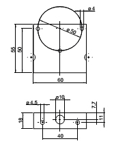
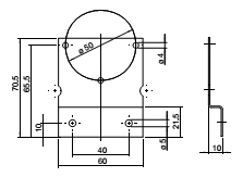
| Metal mounting bracket, S-shaped | Article no. 6402 |
|---|---|
| Metal mounting bracket, L-shaped | Article no. 6401 |
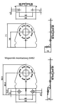
| Snap-on plastic bracket, S-shaped | Article no. 6482 |
| Snap-on plastic bracket, L-shaped | Article no. 6481 |
| Climaset ® consisting of 2 m PVC hose and two plastic tubes | Article no. 6555 |
| Climaset ® consisting of 2 m silicone hose and two plastic tubes | Article no. 6557 |
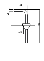
| Climaset ® consisting of 2 m PVC hose and two angled metal pipes | Article no. 6550 |
| Climaset ® consisting of 2 m silicone hose and two angled metal pipes | Article no. 6556 |
| Set consisting of three push-on screw terminals, bagged, | Article no. 6415 |
| Plastic tube for Climaset ® 6555 | Article no. 6551 |
| Angled metal pipe for Climaset ® 6550 | Article no. 6552 |
| Rubber grommet for Climaset ® 6550 | Article no. 6553 |
| Roll with 100 m PVC/silicone hose | Article no. 6424/25 |
| PG-11 cable conduit including sealing and counter screw | Article no. 6358 |
| M20x1.5 cable conduit including sealing and counter screw | Article no. 6568 |
| Cardbox for single packing for 930.8x Climair ® small/large | Article no. 6428/29 |
| 930.8x Climair | Mounting bracket 6481 |
 |
 |
| Climase 6550/6556 | Climase 6555/6557 | Mounting bracket 6401 | Mounting bracket 6402 |
 |
 |
 |
 |
Interessieren Sie sich für dieses Produkt? Benötigen Sie zusätzliche Informationen oder individuelle Preise?
Sie müssen eingeloggt sein
With adjustable switching pressure for Ex zones 1 and 2
Applications
Adjustable differential pressure switch for monitoring overpressure, vacuum and differential pressure of air or other non-aggressive, combustible gases.
Possible fields of application include:
Technical Specifications:
| Medium | air, (non-)combustible and non-aggressive gases |
| Temperature ranges: | |
| Medium and ambient temperature | -20˚C do +85 ˚C |
| Storage temperature | -40˚C do +85 ˚C |
| Switching pressure ranges | 20-200Pa (minimum) |
| 1,000-4,000 (maximum) | |
| Switching differential | 10 Pa minimum |
| 250 Pa maximum (depending on pressure range) | |
| Switching pressure tolerance | ±15% from setpoint |
| Max. working overpressure | 10kPa |
| Pressure connections | 2 plastic hose ports |
| Outer diameter | 6mm |
| Materials: | |
| Diaphragm | silicone, tempered at 200° C, free of gas emissions (other materials on request). |
| Pressure switch housing | PA 6.6 |
| Cover | PS |
| Weight | 150/110 g (with/without cover) |
| Electrical rating | 24 VDC/100 mA; 30 VDC/45 mA |
| Electrical connections | AMP flat plug, 6.3 mm x 0.8 mm, in accordance with DIN 46244 or push-on screw terminals |
| Cable conduit | PG-11 or M20 x1.5 with cable strain relief |
| Protection category | IP 54 (with cover) |
| Mechanical working life | over 106 switching operations |
ATEX
| EC type examination | BVS 06 ATEX E 141X |
| Device category | II 2G |
| Ignition protection type | II B T4 |
| CE conformity | ATEX Directive 94/9/EG |
| RoHS-Directive 2002/95/EG |
This pressure switch can be used in potentially explosive zones 1 and 2. In the safe area, an associated isolating means (separating barrier, switching amplifier) must be connected before. The entire isolating circuit must then be proved to keep inherent safety.
For this purpose, the power specifications (P, I, U) of the barrier must be lower and the characteristics (L, C) higher than those of the pressure switch and of the connection line (blue colour).
Characteristics for IIB:
Voltage- Ui 24VDC/30VDC
Current-Ii 100mA/45mA
Capacitance -Ci 0μF
Inductance -Li 0mH


| Switching pressure setting range [Pa] |
Switching differential set to |
Tolerance for max. and min. switching pressure |
930,8 | EX | ||||||||
|---|---|---|---|---|---|---|---|---|---|---|---|---|
| from | to | |||||||||||
| 20 | 200 | 10 | ±15% | 0 | ||||||||
| 30 | 400 | 15 | ±15% | 4 | ||||||||
| 50 | 500 | 20 | ±15% | 3 | ||||||||
| 200 | 1,000 | 100 | ±15% | 5 | ||||||||
| 500 | 2,500 | 150 | ±15% | 6 | ||||||||
| 1,000 | 4,000 | 250 | ±15% | 7 | ||||||||
| Electrical connection using 6.3 x 0.8 mm flat plug | 1 | |||||||||||
| Electrical connection using enclosed screw terminals | 4 | |||||||||||
| Fitting method using fastening eyes | 2 | |||||||||||
| Scale in mbar | 1 | |||||||||||
| Scale in Pasca | 2 | |||||||||||
| Scale in Pascal and inWC | 3 | |||||||||||
| IP 54 with cable conduit PG-11 | 1 | |||||||||||
| IP 54 with cable conduit M20 x1.5 | 2 | |||||||||||
| Packaging | bulk packed, 45 pcs. per carton | 1 | ||||||||||
| bulk packed, folding boxes included | 2 | |||||||||||
| individually boxed | 3 | |||||||||||
| Accessories | without accessories | 1 | ||||||||||
| with S-shaped metal mounting bracket 6402 | 2 | |||||||||||
| with L-shaped metal mounting bracket 6401 | 3 | |||||||||||
| with Climaset ® 6555 | 4 | |||||||||||
| with Climaset ® 6550 | 5 | |||||||||||
| with metal mounting bracket 6402 and Climaset ® 6555 | 6 | |||||||||||
| with metal mounting bracket 6402 and Climaset ® 6550 | 7 | |||||||||||
| with metal mounting bracket 6401 and Climaset ® 6555 | 8 | |||||||||||
| with metal mounting bracket 6401 and Climaset ® 6550 | 9 | |||||||||||
| with S-shaped snap-on mounting bracket 6482 | A | |||||||||||
| with L-shaped snap-on mounting bracket 6481 | B | |||||||||||
| with snap-on mounting bracket 6482 and Climaset ® 6555 | C | |||||||||||
| with snap-on mounting bracket 6482 and Climaset ® 6550 | D | |||||||||||
| with snap-on mounting bracket 6481 and Climaset ® 6555 | E | |||||||||||
| with snap-on mounting bracket 6481 and Climaset® 6550 | F | |||||||||||
The switching pressure details are referred to a vertical installation position which is also recommended for pressure switches which have their connection ports below. For a horizontal installation position with AMP terminal lugs on top, the switching values are some 20 Pa higher.
The switching pressure can be set without any manometer by an adjusting knob provided with a reference scale. With the aid of a screwdriver, the switching difference can also be adjusted.
| Metal mounting bracket, S-shaped | Article no. 6402 |
|---|---|
| Metal mounting bracket, L-shaped | Article no. 6401 |
| Snap-on plastic bracket, S-shaped | Article no. 6482 |
| Snap-on plastic bracket, L-shaped | Article no. 6481 |
| Climaset ® consisting of 2 m PVC hose and two plastic tubes | Article no. 6555 |
| Climaset ® consisting of 2 m silicone hose and two plastic tubes | Article no. 6557 |
| Climaset ® consisting of 2 m PVC hose and two angled metal pipes | Article no. 6550 |
| Climaset ® consisting of 2 m silicone hose and two angled metal pipes | Article no. 6556 |
| Set consisting of three push-on screw terminals, bagged, | Article no. 6415 |
| Plastic tube for Climaset ® 6555 | Article no. 6551 |
| Angled metal pipe for Climaset ® 6550 | Article no. 6552 |
| Rubber grommet for Climaset ® 6550 | Article no. 6553 |
| Roll with 100 m PVC/silicone hose | Article no. 6424/25 |
| PG-11 cable conduit including sealing and counter screw | Article no. 6358 |
| M20x1.5 cable conduit including sealing and counter screw | Article no. 6568 |
| Cardbox for single packing for 930.8x Climair ® small/large | Article no. 6428/29 |
| 930.8x Climair | Mounting bracket 6481 |
 |
 |
| Climase 6550/6556 | Climase 6555/6557 | Mounting bracket 6401 | Mounting bracket 6402 |
 |
 |
 |
 |
Your review appreciation cannot be sent
Report comment
Report sent
Your report cannot be sent
Eigenen Kommentar verfassen
Review sent
Your review cannot be sent
