
Category


Photos are for informational purposes only. View product specification
please use latin characters
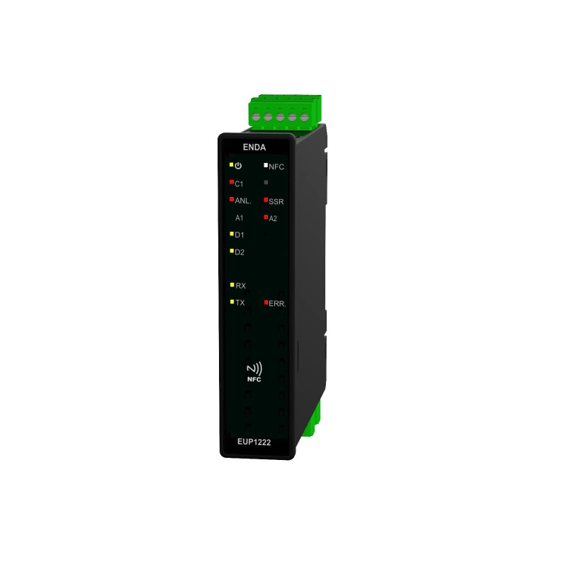
Universal, rail-mounted, NFC-compatible PID controller
Technical Specification

Before the system's first operation, if the PID parameters are known, they should be entered; otherwise, the self-tuning function should be activated.
Technical Data
| Parameter | Value |
| Power Supply | 24V DC |
| Maximum Power Consumption | 5VA |
| Connection | 1.5mm2 screw terminal |
| Maximum Terminal Connection Resistance | 100Ω for thermocouple, 20Ω for three-wire PT100 |
| Ambient/Storage Temperature | 0…+50°C/-25…+70°C (non-condensing) |
| Protection Class | Compliant with EN 60529 IP20 |
| Hysteresis | Adjustable range 1…50°C/F |
Inputs
| Parameter | Value |
| Power Supply | 24V DC |
| Maximum Power Consumption | 5VA |
| Connection | 1.5mm2 screw terminal |
| Maximum Terminal Connection Resistance | 100Ω for thermocouple, 20Ω for three-wire PT100 |
| Ambient/Storage Temperature | 0…+50°C / -25…+70°C (non-condensing) |
| Protection Class | Compliant with EN 60529 IP20 |
| Hysteresis | Adjustable range 1…50°C/F |
Inputs
| Universal sensor inputs | See Sensor Inputs table (rows 1-3) | |
| Potential-free contact input D1 | Programmable input 1 for control button | See Sensor Inputs table (row 4) |
| Potential-free contact input D2 | Programmable input 2 for control button | See Sensor Inputs table (row 4) |
Outputs
| Output C/A2 | Relay: 250 V AC, 5 A (for resistive load), NO (control or Alarm2 output selection) |
| Output A1 | Relay: 250 V AC, 5 A (for resistive load), NO control |
| ANL/SSR outputs | Selectable analog output 0-20mA and 4-20mA; SSR 15V 20mA Maximum load resistance is 500Ω on mA output and in SSR mode |
| Relay lifetime | 10,000,000 operations without load; 250 V AC, 5 A (resistive load) 300,000 operations |
Housing
| Housing type | DIN rail-mounted housing compliant with DIN 43 700 |
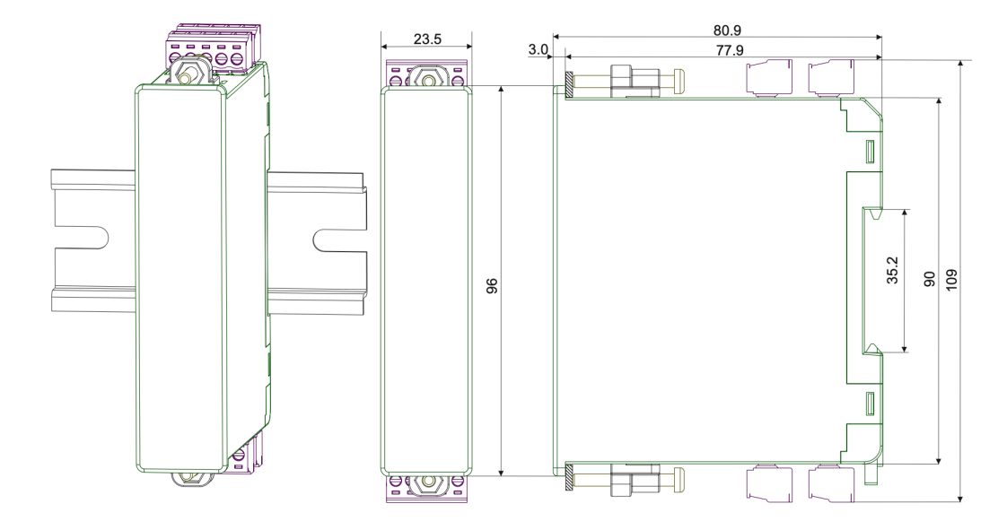
| Dimensions (width x height x depth) | 22.5 x 96 x 86 mm |
| Weight | approx. 158 g (packed) |
| Housing material | Self-extinguishing plastic |
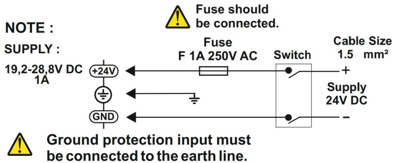
Wiring Diagram


Translation:
Note – Uwaga
Supply – Zasilanie
Fuse should be connected. – Bezpiecznik powinien być podłączony.
Fuse – bezpiecznik
Switch – przełącznik
Cable size – rozmiar przewodu
Ground protection input must be connected to the earth line. – Wejście uziemiające musi być podłączone do linii uziemienia.
 |
• Thermocouples type J-K-L-T-S-R: Use appropriate compensation cables for thermocouples. Do not use jointed cables. Ensure input terminals are connected correctly with proper polarity as shown in the figure. |
 |
• Resistance (Pt100) thermocouples: For two-wire PT100 sensors, short-circuit terminals 2 and 3. Do not use jointed cables. Long cables cause incorrect temperature measurement. |
 |
• Inputs: 0-20mA, 4-20mA, 0-10V, 2-10V, 0-25mV, 0-50mV: Ensure correct connection and proper polarity at the input terminals as shown in the figure. Do not use jointed cables. Long cables cause incorrect measurement results. |
 |
• Potential-free contact inputs D1 and D2: Potential-free contacts must be used with mechanical keys. |
Dimensions (in mm)

Controller Programming
The controller can be programmed via the ENDALink application by bringing a phone with NFC function close. All parameters can be read and configured in the application. A detailed description of the parameters is in the catalog note. QR codes for scanning and installing the application:


Are you interested in this product? Do you need additional information or individual pricing?
Universal, rail-mounted, NFC-compatible PID controller
Technical Specification

Before the system's first operation, if the PID parameters are known, they should be entered; otherwise, the self-tuning function should be activated.
Technical Data
| Parameter | Value |
| Power Supply | 24V DC |
| Maximum Power Consumption | 5VA |
| Connection | 1.5mm2 screw terminal |
| Maximum Terminal Connection Resistance | 100Ω for thermocouple, 20Ω for three-wire PT100 |
| Ambient/Storage Temperature | 0…+50°C/-25…+70°C (non-condensing) |
| Protection Class | Compliant with EN 60529 IP20 |
| Hysteresis | Adjustable range 1…50°C/F |
Inputs
| Parameter | Value |
| Power Supply | 24V DC |
| Maximum Power Consumption | 5VA |
| Connection | 1.5mm2 screw terminal |
| Maximum Terminal Connection Resistance | 100Ω for thermocouple, 20Ω for three-wire PT100 |
| Ambient/Storage Temperature | 0…+50°C / -25…+70°C (non-condensing) |
| Protection Class | Compliant with EN 60529 IP20 |
| Hysteresis | Adjustable range 1…50°C/F |
Inputs
| Universal sensor inputs | See Sensor Inputs table (rows 1-3) | |
| Potential-free contact input D1 | Programmable input 1 for control button | See Sensor Inputs table (row 4) |
| Potential-free contact input D2 | Programmable input 2 for control button | See Sensor Inputs table (row 4) |
Outputs
| Output C/A2 | Relay: 250 V AC, 5 A (for resistive load), NO (control or Alarm2 output selection) |
| Output A1 | Relay: 250 V AC, 5 A (for resistive load), NO control |
| ANL/SSR outputs | Selectable analog output 0-20mA and 4-20mA; SSR 15V 20mA Maximum load resistance is 500Ω on mA output and in SSR mode |
| Relay lifetime | 10,000,000 operations without load; 250 V AC, 5 A (resistive load) 300,000 operations |
Housing
| Housing type | DIN rail-mounted housing compliant with DIN 43 700 |
| Dimensions (width x height x depth) | 22.5 x 96 x 86 mm |
| Weight | approx. 158 g (packed) |
| Housing material | Self-extinguishing plastic |
Wiring Diagram


Translation:
Note – Uwaga
Supply – Zasilanie
Fuse should be connected. – Bezpiecznik powinien być podłączony.
Fuse – bezpiecznik
Switch – przełącznik
Cable size – rozmiar przewodu
Ground protection input must be connected to the earth line. – Wejście uziemiające musi być podłączone do linii uziemienia.
 |
• Thermocouples type J-K-L-T-S-R: Use appropriate compensation cables for thermocouples. Do not use jointed cables. Ensure input terminals are connected correctly with proper polarity as shown in the figure. |
 |
• Resistance (Pt100) thermocouples: For two-wire PT100 sensors, short-circuit terminals 2 and 3. Do not use jointed cables. Long cables cause incorrect temperature measurement. |
 |
• Inputs: 0-20mA, 4-20mA, 0-10V, 2-10V, 0-25mV, 0-50mV: Ensure correct connection and proper polarity at the input terminals as shown in the figure. Do not use jointed cables. Long cables cause incorrect measurement results. |
 |
• Potential-free contact inputs D1 and D2: Potential-free contacts must be used with mechanical keys. |
Dimensions (in mm)

Controller Programming
The controller can be programmed via the ENDALink application by bringing a phone with NFC function close. All parameters can be read and configured in the application. A detailed description of the parameters is in the catalog note. QR codes for scanning and installing the application:


Your review appreciation cannot be sent
Report comment
Report sent
Your report cannot be sent
Write your review
Review sent
Your review cannot be sent
