-
-
-
Category
-
Semiconductors
- Diodes
- Thyristors
-
Electro-insulated Modules
- Electro-insulated Modules | VISHAY (IR)
- Electro-insulated Modules | INFINEON (EUPEC)
- Electro-insulated Modules | Semikron
- Electro-insulated Modules | POWEREX
- Electro-insulated Modules | IXYS
- Electro-insulated Modules | POSEICO
- Electro-insulated Modules | ABB
- Electro-insulated Modules | TECHSEM
- Go to the subcategory
- Bridge Rectifiers
-
Transistors
- Transistors | GeneSiC
- SiC MOSFET Modules | Mitsubishi
- SiC MOSFET Modules | STARPOWER
- Module SiC MOSFET ABB’s
- IGBT Modules | MITSUBISHI
- Transistor Modules | MITSUBISHI
- MOSFET Modules | MITSUBISHI
- Transistor Modules | ABB
- IGBT Modules | POWEREX
- IGBT Modules | INFINEON (EUPEC)
- Silicon Carbide (SiC) semiconductor elements
- Go to the subcategory
- Gate Drivers
- Power Blocks
- Go to the subcategory
- Electrical Transducers
-
Passive components (capacitors, resistors, fuses, filters)
- Resistors
-
Fuses
- Miniature Fuses for electronic circuits - ABC & AGC Series
- Tubular Fast-acting Fuses
- Time-delay Fuse Links with GL/GG & AM characteristics
- Ultrafast Fuse Links
- Fast-acting Fuses (British & American standard)
- Fast-acting Fuses (European standard)
- Traction Fuses
- High-voltage Fuse Links
- Go to the subcategory
- Capacitors
- EMI Filters
- Supercapacitors
- Power surge protection
- Go to the subcategory
-
Relays and Contactors
- Relays and Contactors - Theory
- 3-Phase AC Semiconductor Relays
- DC Semiconductor Relays
- Controllers, Control Systems and Accessories
- Soft Starters and Reversible Relays
- Electromechanical Relays
- Contactors
- Rotary Switches
-
Single-Phase AC Semiconductor Relays
- AC ONE PHASE RELAYS 1 series| D2425 | D2450
- One phase semiconductor AC relays CWA and CWD series
- One phase semiconductor AC relays CMRA and CMRD series
- One phase semiconductor AC relays - PS series
- Double and quadruple semiconductor AC relays - D24 D, TD24 Q, H12D48 D series
- One phase semiconductor relays - gn series
- Ckr series single phase solid state relays
- One phase AC semiconductor relays for DIN bus - ERDA I ERAA series
- 150A AC single phase relays
- Rail Mountable Solid State Relays With Integrated Heat Sink - ENDA, ERDA1 / ERAA1 series
- Go to the subcategory
- Single-Phase AC Semiconductor Relays for PCBs
- Interface Relays
- Go to the subcategory
- Cores and Other Inductive Components
- Heatsinks, Varistors, Thermal Protection
- Fans
- Air Conditioning, Accessories for Electrical Cabinets, Coolers
-
Batteries, Chargers, Buffer Power Supplies and Inverters
- Batteries, Chargers - Theoretical Description
- Modular Li-ion Battery Building Blocks, Custom Batteries, BMS
- Batteries
- Battery Chargers and Accessories
- Uninterruptible Power Supply and Buffer Power Supplies
- Inverters and Photovoltaic Equipments
- Energy storage
- Fuel cells
- Lithium-ion batteries
- Go to the subcategory
-
Automatics
- Futaba Drone Parts
- Limit Switches, Microswitches
- Sensors, Transducers
-
Infrared Thermometers (Pyrometers)
- IR-TE Series - Water-proof Palm-sized Radiation Thermometer
- IR-TA Series - Handheld Type Radiation Thermometer
- IR-H Series - Handheld Type Radiation Thermometer
- IR-BA Series - High-speed Compact Radiation Thermometer
- IR-FA Series - Fiber Optic Radiation Thermometer
- IR-BZ Series - Compact Infrared Thermometers
- Go to the subcategory
- Counters, Time Relays, Panel Meters
- Industrial Protection Devices
- Light and Sound Signalling
- Thermographic Camera
- LED Displays
- Control Equipments
-
Recorders
- Hybrid Recorders - AL3000 Series | CHINO
- Graphic Recorder - KR2000 Series | CHINO
- Ubiquitous Recorders - KR5000 Series | CHINO
- Palm-sized Temperature/Humidity Meters - HN-CH Series | CHINO
- Consumables for Recorders
- 71VR1 - Compact Paperless Recorder | M-SYSTEM
- Graphic Recorder - KR3000 Series | CHINO
- PC Recorders - R1M Series | M-SYSTEM
- PC Recorders - R2M Series | M-SYSTEM
- PC Recorders - RZMS Series | M-SYSTEM
- PC Recorders - RZUS Series | M-SYSTEM
- Go to the subcategory
- Go to the subcategory
-
Cables, Litz wires, Conduits, Flexible connections
- Wires
- Litz wires
- Cables for extreme applications
- Sleevings
-
Braids
- Flat Braids
- Round Braids
- Very Flexible Flat Braids
- Very Flexible Round Braids
- Cylindrical Cooper Braids
- Cylindrical Cooper Braids and Sleevings
- Flexible Earthing Connections
- Galvanized and Stainless Steel Cylindrical Braids
- PCV Insulated Copper Braids (temp. up to 85C)
- Flat Aluminium Braids
- Junction Set - Braids and Tubes
- Go to the subcategory
- Traction Equipment
- Cable Terminals
- Flexible Insulated Busbars
- Flexible Multilayer Busbars
- Cable Duct Systems
- Hoses
- Go to the subcategory
- View all categories
-
Semiconductors
-
-


Towards a Greener Future: Highly Efficient SiC Power Devices for Wide Application Range

Towards a Greener Future: Highly Efficient SiC Power Devices for Wide Application Range
In various applications, SiC devices are used today to achieve highly efficient and compact converters. Applications range all power ratings, from air conditioners, to battery chargers, to industrial drives and even railway propulsion. This article discusses the demands from different applications, highlights the MITSUBISHI ELECTRIC SiC power devices available in different voltage and power classes and gives insights in latest developments.
By René Spenke, Mitsubishi Electric Europe B.V., Ratingen, Germany Nils Soltau, Mitsubishi Electric Europe B.V., Ratingen, Germany Toru Matsuoka, Mitsubishi Electric Corporation, Fukuoka, Japan
Introduction
The reduction of carbon dioxide and the responsible use of electric energy are main drivers for a more sustainable future society. Silicon Carbide (SiC) and its superior physical properties shall save even more electric energy and make power-electronic converters more compact, which reduces the consumption of valuable materials and resources.
The main difference between SiC semiconductors and classical silicon is the higher band gap. This allows 10-times higher critical field strength in the SiC material. Consequently, for the same blocking-voltage capability, SiC chips can be made thinner. Hence, electrical resistance and power losses are decreased.
Furthermore, due to the higher band gap, SiC MOSFETs or SiC Schottky Barrier Diodes can be produced even for higher blocking voltages (e.g. 3300 V or 6500 V). Due to high switching speed, these unipolar devices have low switching losses and enable high switching frequencies. In many applications, the higher switching frequencies yields power-density increase of other system components, like filters, transformers or motors. Hence, the power-electronic converter becomes more compact and saves material and related costs.
Since the 1990s, Mitsubishi Electric has gained comprehensive experience about the production and application of SiC devices and power modules. SiC power semiconductors have successfully completed the technology hype cycle and Mitsubishi Electric SiC products are widely available. Today, we find SiC products in various applications: from chargers for electric vehicles, to air conditioners, to uninterruptable power supplies, to industrial drives and even railway traction drives. These different applications result different requirements to the SiC device. This article demonstrates the variety of demands and the according SiC solution.
The Core of our SiC Devices: Next Generation of SiC chips
The newest SiC devices feature Mitsubishi Electric’s 2nd generation of SiC chips. These chips are manufactured on the new 6-inch SiC wafer line. As shown in Figure 1, the 2nd generation has an enhanced planar MOSFET structure. The special JFET doping profile enables improvement of the specific electric resistance Ron,sp while reducing the MOSFET cell width as demonstrated in Figure 2. The excellent electric resistance of this enhanced planar MOSFET technology is highly competitive against other trench gate structures as shown in Figure 3.
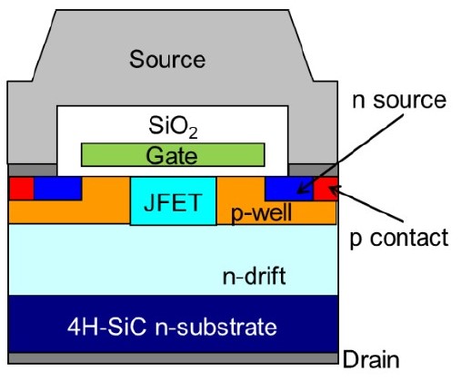
Figure 1: Structure of 2nd Generation SiC MOSFET Chip
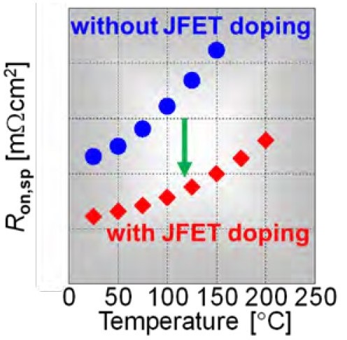
Figure 2: Unique JFET doping improves Ron,sp
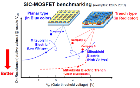
Figure 3: Comparison between different Planar- and Trench-Gate SiC MOSFET technologies
Moreover, the JFET doping lowers the reverse transfer capacitance Crss. This capacitance affects the switching speed of the SiC device. The smaller Crss allows higher switching speeds and improves robustness against parasitic turn-on as explained further below.
Integrated SiC DIPIPM power module solutions increasing the efficiency of air conditioners
For the lower power inverters, Mitsubishi Electric introduced SiC DIPIPM power devices with blocking voltage capability of 600 V and two different current ratings: 15 A and 25 A. This class of intelligent power modules contains the relevant components such as six switches and gate driver ICs to build compact inverters (cf. Figure 9). The intelligence of these products are the integrated protection functions, such as short-circuit protection, under-voltage lockout or over-temperature protection. As shown in Figure 8, the modules are manufactured using transfer molded technology, which allows to secure high productivity and robustness against influence of aggressive environments. Especially applications running almost 24 hours per day, such as air conditioners or pumps, can benefit from the increase of efficiency by applying SiC. Figure 10 shows a comparison to conventional silicon device and how 70% of converter power loss can be saved under regarded operating conditions.
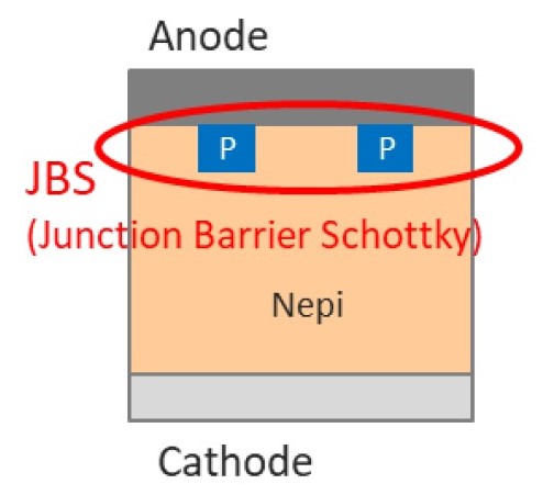
Figure 6: Structure of Mitsubishi Electric's Junction Barrier Schottky Diode
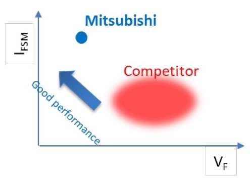
Figure 7: Diode Trade-off comparison (VF vs. IFSM)
SiC Power Modules for Uninterruptable Power Supplies, Fast Chargers and Efficient Feed-In of Renewables
Applications like uninterruptable power supplies, fast chargers or the feed-in of renewable energy sources usually require much higher current ratings than discussed before. Therefore, Mitsubishi Electric has developed SiC power modules, that also feature the 2nd generation chip technology [5]. These modules offer the benefits of SiC technology to industrial applications requiring high currents, beyond the capability of discrete devices. Available are voltage classes of 1200 V and 1700 V and a wide line-up of current ratings up to 1200 A. As shown in Figure 11, the 2nd generation power modules are packagecompatible to the 1st generation, allowing our customers an easier development based on their existing designs.
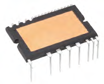
Figure 8: Super Mini Full SiC DIPIPM
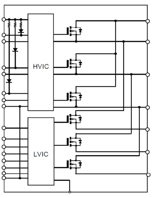
Figure 9: SiC DIPIPM internal block diagram
Key Features:
With 122 x 79.6 mm², the footprint of the modules is the same as Mitsubishi Electric’s NX-series power modules. However, to reduce the parasitic loop inductance of the package significantly, the terminals were re-arranged, allowing a better utilization of the benefits of the SiC technology. Additionally, the design of the baseplate and the placement of the SiC-MOSFET and SiC-SBD chips was optimized to improve the heat spreading inside the package.
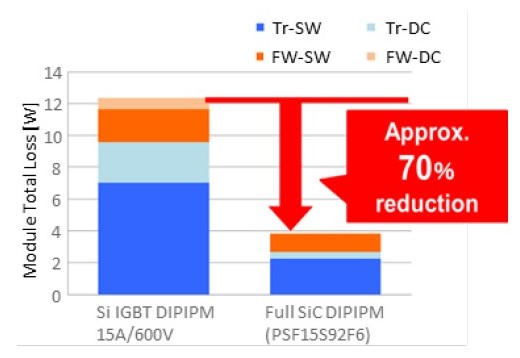
Figure 10: SiC DIPIPM benchmark (Vcc=300V, VD=18V(SiC) /15V(Si), fc=15kHz, PF=0.95, M=0.8, Io=1.5Arms,Tj=125°)
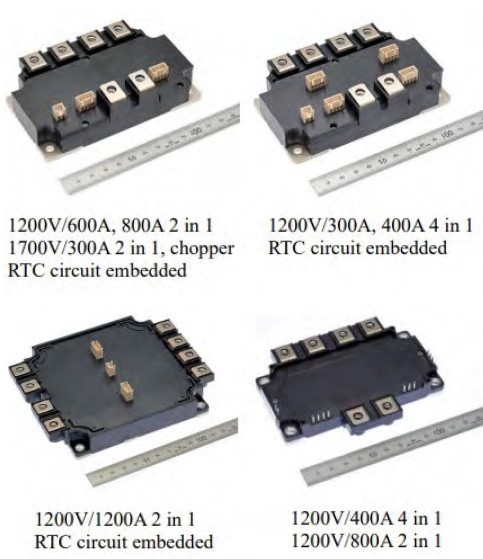
Figure 11: Industrial SiC power modules' line up
| Model | Rated Voltage |
Rated Current |
Circuit Structure |
RTC circuit |
Size |
| FMF400BX-24B | 1200 V | 400 A | 4 in 1 | No | 121.7 x 92.3 |
| FMF800DX-24B | 800 A | 2 in 1 | No | ||
| FMF300BXZ-24B | 300 A | 4 in 1 | Yes | 122 x 79.6 | |
| FMF400BXZ-24B | 400 A | Yes | |||
| FMF600DXZ-24B | 600 A | 2 in 1 | Yes | ||
| FMF800DXZ-24B | 800 A | Yes | |||
| FMF1200DXZ-24B | 1200 A | Yes | 122 x 152 | ||
| FMF300DXZ-34B | 1700 V | 300 A | 2 in 1 | Yes | 122 x 79.6 |
| FMF300E3XZ-34B | 300 A | Chopper | Yes |
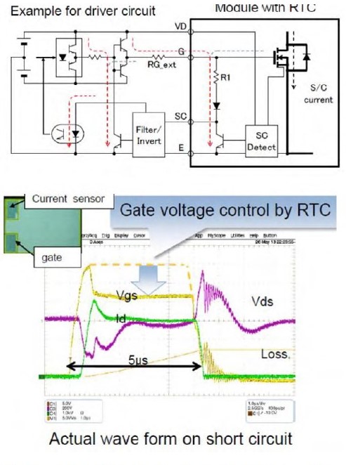
Figure 12: Efficient short circuit detection by RTC function
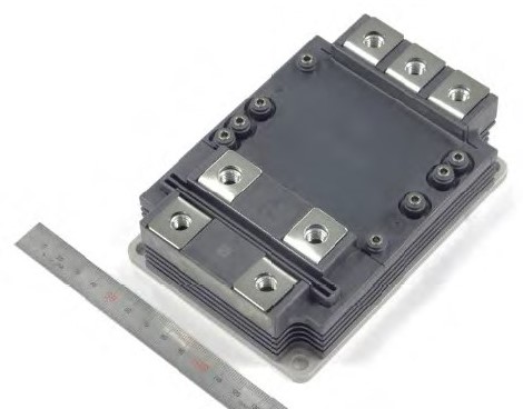
Figure 13: 3.3 kV Full-SiC power module in LV100 package with 6 kV insulation voltage
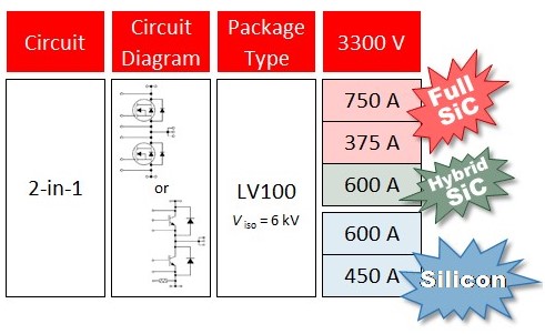
Figure 14: Lineup of 3.3 kV SiC and Si power modules in LV100 package
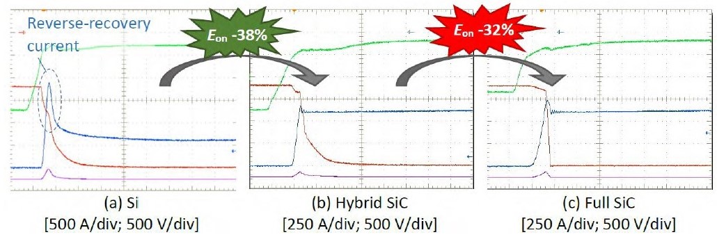
Figure 15: Comparison of turn-on waveforms between silicon (Si), hybrid SiC and Full-SiC (Vcc = 1800 V, IC = 600A, Tj = 150 °C, Ls = 65 nH)
The 2nd generation with the previously described JFET doping technology offers lowest overall losses. Compared to the 1st generation, both, the conduction and the switching losses were further reduced [6].
Mitsubishi Electric’s Real-Time Control (RTC) function eases the design of short circuit protection. The design of short-circuit protection is a challenge when changing from IGBTs to SiC MOSFETs, as methods such as desaturation detection cannot be applied in the same way. To overcome these constraints, the RTC function detects a short circuit using current sensors integrated into the MOSFETs. When a short circuit is detected, the gate voltage is automatically reduced to limit the current and increase the short-circuit withstand time. This gives enough time to the driver circuit to react on the short circuit signal from the RTC function.
High-Voltage SiC Modules for Railway and Grid Applications
In this bullet train operation, SiC power modules allow a more efficient and more compact traction system. As an example, SiC power modules have enabled 20% weight savings in the Shinkansen drive train, leading to a more flexible railroad car designed. The volume of the traction inverter itself was reduced by 50% which was enabled by the lower losses of SiC devices leading to a simpler cooling system [7].
Besides traction inverters, auxiliary converters, railway battery chargers and dc-dc converters especially benefit from the switching frequency increase enabled by SiC power modules. The increasing switching frequency typically allows the size reduction of passive components (like transformers, inductors or capacitors). Moreover, the higher switching frequency might allow the use of different soft-magnetic core materials. It gives the potential for efficiency increase and cost reduction [8] [9].
With increasing voltage and power ratings, railway and grid applications demand for best performance and highest reliability. Mitsubishi Electric offers commercial high-power SiC modules for voltages up to 3.3 kV for high-reliability application. Already in 2015, Mitsubishi Electric has applied 3.3 kV Full- SiC semiconductor modules in high-speed bullet trains [10]. Hence, the robustness of these devices has been demonstrated under real conditions by several years of field operation.
![Structure of a conventional MOSFET and one with embedded SBD [12]](https://www.dacpol.eu/img/cms/Baza%20Wiedzy/Mitsubishi/17/Figure16.jpg)
Figure 16: Structure of a conventional MOSFET and one with embedded SBD [12]
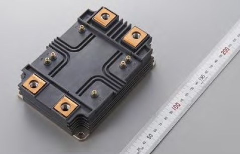
Figure 17: 6.5 kV Full-SiC power module in HV100 package with 10.2 kV insulation voltage
Mitsubishi Electric offers its 3.3 kV SiC power modules in the LV100 package as depicted in Figure 13. As shown in Figure 14, two different Full-SiC products are available with current ratings of 375 A and 750 A.
Additionally to Full-SiC Power Modules, Mitsubishi Electric also offers Hybrid-SiC modules. In the same LV100 package, a 600 A Hybrid- SiC module for 3.3 kV is available. This device combines an silicon High-Voltage IGBT of the latest X-Series generation with a SiC diode. Compared to the Si diode, the SiC diode is reverse-recovery free. Hence, the switching losses in the diode are much smaller. Moreover, the losses in the IGBT are reduced as well due to the absence of the reverse recovery current. As shown in Figure 15, IGBT turn-on losses are 38% lower. This makes the hybrid SiC power module the ideal candidate for relatively high switching frequencies (e.g. around 2 kHz). If higher switching frequency and lower losses are required, then Full-SiC power modules are the perfect choice.
![Comparison of switching loss between Si-IGBT at 150°C, SiC-MOSFET and SBD-embedded SiC-MOSFET at 175°C [13]](https://www.dacpol.eu/img/cms/Baza%20Wiedzy/Mitsubishi/17/Figure18.png)
Figure 18: Comparison of switching loss between Si-IGBT at 150°C, SiC-MOSFET and SBD-embedded SiC-MOSFET at 175°C [13]
Beyond existing SiC products, Mitsubishi Electric is further developing SiC technology to become even more competitive in future. One research topic is related to the integration of the SiC SBD diode in the MOSFET structure. Generally, the SBD diode is required to avoid bipolar current flow through the body diode of the MOSFET. Hence, degradation effects like stacking faults are suppressed. To achieve this in today’s SiC power modules, dedicated SBD diode chips are connected in parallel to the MOSFET chips. In future, the SBD structure is integrated into the MOSFET chip as shown in Figure 16. Additional benefits, besides avoidance of stacking fault, are lower switching losses and the omission of dedicated diode chips [11] [12].
The technology of embedding the SBD is also utilized in the 6.5 kV Full-SiC prototype [13]. This prototype utilizes the HV100 package as show in Figure 17 and is rated for 400 A. As shown in Figure 18, the switching losses of this device are less than 1/10 compared to a Si IGBT. This gives 6.5 kV SiC devices enormous potential for highswitching frequency applications.
Conclusion
This article has shown that today many applications benefit from the advantages of SiC devices, which result in more efficient and more compact power converters. All these different applications make different demands on the SiC devices. It has been shown that Mitsubishi Electric offers particular SiC products for nearly every application.
Acknowledgement
This work was supported by the New Energy and Industrial Technology Development Organization (NEDO).
References
[1] Mitsubishi Electric Press Release No. 3361, Mitsubishi Electric to Launch N-series 1200 V SiC-MOSFET, Japan, 2020.
[2] Mitsubishi Electric , „Reduce Space and Increase Efficiency with the N-Series 1200V SiC-MOSFET,“ Bodo's Power System, p. 14, September 2020.
[3] Mitsubishi Electric Press Release No. 3382, Mitsubishi Electric to Launch 4-terminal N-series 1200V SiC-MOSFETs, Japan, 2020.
[4] Mitsubishi Electric Press Release No. 3272, Mitsubishi Electric to Launch 1200V SiC Schottky Barrier Diode, Japan, 2019.
[5] Mitsubishi Electric Press Release No. 3372, Mitsubishi Electric to Launch Second-generation Full-SiC Power Modules for Industrial Use, Japan, 2020.
[6] N. Soltau, E. Thal und T. Matsuoka, „The Next Generation of SiC Power Modules,“ Bodo's Power Systems, pp. 22-26, September 2019.
[7] K. Sato, H. Kato und T. Fukushima, „Development of SiC Applied Traction System for Shinkansen High-speed Train,“ in International Power Electronics Conference (IPEC-Niigata 2018 -ECCE Asia), Niigata, 2018.
[8] M. Helsper und M. Ocklenburg, „SiC MOSFET Based Auxiliary Power Supply for Rail Vehicles,“ in 20th European Conference on Power Electronics and Applications (EPE'18 ECCE Europe), Riga, 2018.
[9] D. Wu, C. Xiao, H. Zhang und W. Liang, „Development of auxiliary converter based on 1700V/325A full SiC MOSFET for urban rail transit vehicles,“ in IEEE Transportation Electrification Conference and Expo, Asia-Pacific (ITEC Asia-Pacific), Harbin, 2017.
[10] Mitsubishi Electric Press Release No. 2942, Mitsubishi Electric Installs Railcar Traction System with All-SiC Power Modules on Shinkasen Bullet Train, Japan, 2015.
[11] T. Tominaga, S. Hino, Y. Mitsui, J. Nakashima, K. Kawahara, S. Tomohisa und N. Miura, „Superior Switching Characteristics of SiCMOSFET Embedding SBD,“ in 31st International Symposium on Power Semiconductor Devices & ICs, Shanghai, China, 2019.
[12] T. Murakami, K. Sadamatsu, M. Imaizumi, E. Suekawa und S. Hino, „Comparative study of electrical characteristics between conventional and SBD-embedded MOSFETs for next generation 3.3kV SiC modules,“ in International Exhibition and Conference for Power Electronics, Intelligent Motion, Renewable Energy and Energy Management (PCIM), Germany, 2020.
[13] J. Nakashima und e. al., „6.5-kV Full-SiC Power Module (HV100) with SBD-embedded SiC-MOSFETs,“ in International Exhibition and Conference for Power Electronics, Intelligent Motion, Renewable Energy and Energy Management (PCIM Europe), Germany, 2018.
Related posts
Now available – DC/DC converters from PREMIUM
We introduced a novelty to our permanent offer in DACPOL in the category of power supplies and converters and today...
Read more
New release in DACPOL lighting for lathes – Kira covers
We introduce a new product into the DACPOL category of industrial lighting and today we offer KIRA covers for...
Read more
Leave a comment