-
-
-
Category
-
Semiconductors
- Diodes
- Thyristors
-
Electro-insulated Modules
- Electro-insulated Modules | VISHAY (IR)
- Electro-insulated Modules | INFINEON (EUPEC)
- Electro-insulated Modules | Semikron
- Electro-insulated Modules | POWEREX
- Electro-insulated Modules | IXYS
- Electro-insulated Modules | POSEICO
- Electro-insulated Modules | ABB
- Electro-insulated Modules | TECHSEM
- Go to the subcategory
- Bridge Rectifiers
-
Transistors
- Transistors | GeneSiC
- SiC MOSFET Modules | Mitsubishi
- SiC MOSFET Modules | STARPOWER
- Module SiC MOSFET ABB’s
- IGBT Modules | MITSUBISHI
- Transistor Modules | MITSUBISHI
- MOSFET Modules | MITSUBISHI
- Transistor Modules | ABB
- IGBT Modules | POWEREX
- IGBT Modules | INFINEON (EUPEC)
- Silicon Carbide (SiC) semiconductor elements
- Go to the subcategory
- Gate Drivers
- Power Blocks
- Go to the subcategory
- Electrical Transducers
-
Passive components (capacitors, resistors, fuses, filters)
- Resistors
-
Fuses
- Miniature Fuses for electronic circuits - ABC & AGC Series
- Tubular Fast-acting Fuses
- Time-delay Fuse Links with GL/GG & AM characteristics
- Ultrafast Fuse Links
- Fast-acting Fuses (British & American standard)
- Fast-acting Fuses (European standard)
- Traction Fuses
- High-voltage Fuse Links
- Go to the subcategory
- Capacitors
- EMI Filters
- Supercapacitors
- Power surge protection
- TEMPEST emission revealing filters
- Surge arrester
- Go to the subcategory
-
Relays and Contactors
- Relays and Contactors - Theory
- 3-Phase AC Semiconductor Relays
- DC Semiconductor Relays
- Controllers, Control Systems and Accessories
- Soft Starters and Reversible Relays
- Electromechanical Relays
- Contactors
- Rotary Switches
-
Single-Phase AC Semiconductor Relays
- AC ONE PHASE RELAYS 1 series| D2425 | D2450
- One phase semiconductor AC relays CWA and CWD series
- One phase semiconductor AC relays CMRA and CMRD series
- One phase semiconductor AC relays - PS series
- Double and quadruple semiconductor AC relays - D24 D, TD24 Q, H12D48 D series
- One phase semiconductor relays - gn series
- Ckr series single phase solid state relays
- One phase AC semiconductor relays for DIN bus - ERDA I ERAA series
- 150A AC single phase relays
- Rail Mountable Solid State Relays With Integrated Heat Sink - ENDA, ERDA1 / ERAA1 series
- Go to the subcategory
- Single-Phase AC Semiconductor Relays for PCBs
- Interface Relays
- Go to the subcategory
- Cores and Other Inductive Components
- Heatsinks, Varistors, Thermal Protection
- Fans
- Air Conditioning, Accessories for Electrical Cabinets, Coolers
-
Batteries, Chargers, Buffer Power Supplies and Inverters
- Batteries, Chargers - Theoretical Description
- Modular Li-ion Battery Building Blocks, Custom Batteries, BMS
- Batteries
- Battery Chargers and Accessories
- Uninterruptible Power Supply and Buffer Power Supplies
- Inverters and Photovoltaic Equipments
- Energy storage
- Fuel cells
- Lithium-ion batteries
- Go to the subcategory
-
Automatics
- Spiralift Lifts
- Futaba Drone Parts
- Limit Switches, Microswitches
- Sensors, Transducers
-
Infrared Thermometers (Pyrometers)
- IR-TE Series - Water-proof Palm-sized Radiation Thermometer
- IR-TA Series - Handheld Type Radiation Thermometer
- IR-H Series - Handheld Type Radiation Thermometer
- IR-BA Series - High-speed Compact Radiation Thermometer
- IR-FA Series - Fiber Optic Radiation Thermometer
- IR-BZ Series - Compact Infrared Thermometers
- Go to the subcategory
- Counters, Time Relays, Panel Meters
- Industrial Protection Devices
- Light and Sound Signalling
- Thermographic Camera
- LED Displays
- Control Equipments
- Go to the subcategory
-
Cables, Litz wires, Conduits, Flexible connections
- Wires
- Cable feedthroughs and couplers
- Litz wires
-
Cables for extreme applications
- Extension and Compensation cables
- Thermocouple cables
- Connection cables for PT sensors
- Multi-conductor wires (temp. -60C to +1400C)
- Medium voltage cables
- Ignition wires
- Heating cables
- Single conductor cables (temp. -60C to +450C)
- Railway cables
- Heating cables Ex
- Cables for the defense industry
- Go to the subcategory
- Sleevings
-
Braids
- Flat Braids
- Round Braids
- Very Flexible Flat Braids
- Very Flexible Round Braids
- Cylindrical Cooper Braids
- Cylindrical Cooper Braids and Sleevings
- Flexible Earthing Connections
- PCV Insulated Copper Braids (temp. up to 85C)
- Flat Aluminium Braids
- Junction Set - Braids and Tubes
- Steel Braids
- Go to the subcategory
- Traction Equipment
- Cable Terminals
- Flexible Insulated Busbars
- Flexible Multilayer Busbars
- Cable Duct Systems
- Go to the subcategory
- View all categories
-
Semiconductors
-
-


Robust High Voltage IGBT Power Modules Against Humidity and Condensation

Robust High Voltage IGBT Power Modules Against Humidity and Condensation
Mitsubishi Electric continuously improve the power device robustness even considering different environmental conditions like humidity and condensation.
By Eugen Wiesner, MITSUBISHI ELECTRIC EUROPE B. V.K. Nakamura, K. Hatori, MITSUBISHI ELECTRIC CORPORATION
Introduction
The power electronics is exposed to extreme environmental conditions during the operation like dust, temperature, humidity, vibrations or chemicals. The mission profile of the temperature and relative humidity has a wide range dependent on application and the location of operation.
In some mining applications the relative humidity level reach even almost 100% with condensation, drip and high pressure water spray for dust control [1].
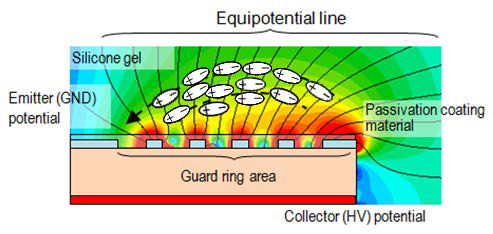
Figure 1: Principle chip guard ring area with gel polarization effect
The IGBT power module as a key components of power electronics is suspended even to such harsh environment. Although the temperature influence on power semiconductor life-time was investigated quite intensively, the humidity was not taken into the account so far due to the missing life-time models or knowledge about failure mechanisms. Especially for case type high voltage IGBT power modules the humidity becomes important parameter due to the non-hermetic package design and the high electric field at semiconductor interfaces, like passivation area. As a result it was necessary to investigate the humidity caused failure mechanisms more deeply and to establish the needed life-time models.
In this article the Mitsubishi Electric investigation results are presented in regards to the humidity and condensation influence on high voltage IGBT power modules durability.
Humidity failure mechanisms and life-time model
The electromechanical migration (ECM) and aluminum corrosion are two possible and well described [2] failure mechanisms of power semiconductors caused by humidity. In the first case (ECM) a dendrite grow of Cu or Ag can be detected on the chip passivation area. In the second case the Aluminum metallization is corroded on the guard-ring.
Besides above described two failure mechanisms caused by humidity and requiring a long time influence Mitsubishi Electric found and published one other failure mechanism that may happen even after short humidity or condensation impact [4]. This failure may appear in case of gel polarization and surface charge accumulation at high voltage above guard ring area. In the figure 1 the principle structure of chip guard ring area with the gel polarization effect is shown. The moisture absorption in the module accelerates the polarization. From the polarization resulting surface charge accumulation above the chip’s guard ring area causes the blocking capability degradation of the device. This may finally lead to device failure.
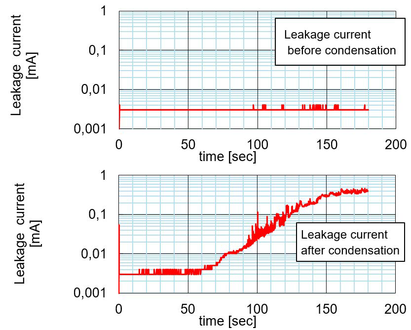
Figure 2: Leakage current increase after condensation event
This phenomenon can be detected by leakage current increase after condensation event. The leakage current increase happens not immediately. It takes several seconds before the current rises after voltage is applied. In figure 2 the comparison of the leakage current characteristic between dry condition and after condensation is shown.
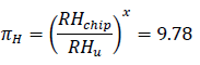
The knowledge of failure mechanism only is not enough to decide whether the power device will operate the desired time under given conditions. That’s why Mitsubishi Electric developed and proposed a life time model considering the humidity as below [2]:
LI is the estimated life time of the power device. The coefficients πH, πT and πV are the acceleration factors proposed by [3]. These factors, can be defined by HV-H3TRB measurements at different conditions. The LTb is the basic life time. It can be calculated from the transformation of different conditions used during the HV-H3TRB evaluation to only one reference condition for example 75%RH, 25°C and 1500V (for 3300V IGBT-Module)
In the following example it is shown how the humidity related parameters can be defined and calculated using 3300V IGBT Module. In the first step the humidity acceleration factor πH can be calculated using the results from two HV-H3TRB tests. One test (test A) was performed at 85% RH the second test (test B) was performed at 95% RH.
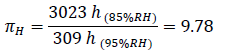
For this calculation the 50% Weibull distribution values were used. Other test parameters like temperature and voltage were kept same for both tests. Detailed evaluation result are shown in figure 3 below.
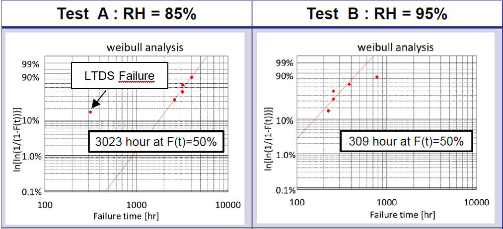
Figure 3: HV-H3TRB evaluation result with 3300V IGBT
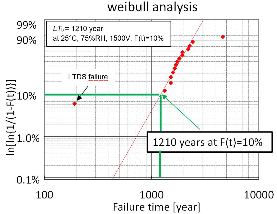
Figure 4: Estimation of basic life-time from HV-H3TRB evaluation test results for 3300V IGBT
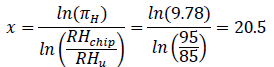
In the second step the empirical factor x using Peck’s model can be calculated as below:
In the final third step each testing point from HV-H3TRB evaluation can be transformed to the base line at reference conditions (75%RH, 25°C, 1500V) to define the basic life time (LTb).
All the transferred testing points from different HV-H3TRB test can be plotted into one Weibull diagram as shown in figure 4. As a result the basic life time can be estimated at the reference conditions fo example considering 10% probability value from this Weibull distribution.
From the established humidity life-time model the user can learn a lot. For example the IGBT-Module life-time curves can be drawn in humidity vs. temperature diagram to investigate the impact of temperature increase on the life-time as shown in figure 5. During the operation the absolute humidity is almost constant on the other hand the temperature is fluctuating. The diagram in figure 5 shows that even small increase of temperature by 4 °C at the same absolute humidity can increase the device life time by 30 times. That is why the starting of the inverter should be carefully considered because of low temperature.
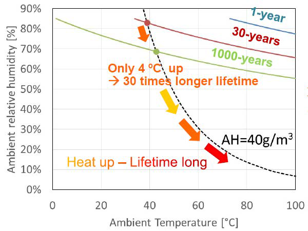
Figure 5: Impact of temperature increase on the module life-time
IGBT-Module condensation test method
The original condensation test method to check power device robustness against condensation was proposed by Mitsubishi Electric in 2015 [4]. Before condensation event the power module was placed into the humidity chamber at the conditions of 85°C and 85%RH for 36 hours. This time is required to ensure that the humidity reached all parts inside the IGBT module. The power device will be like “saturated” with humidity. After the storage in the humidity chamber the samples will be cooled down rapidly from 85°C to 10°C using a heat sink outside the climate chamber. This rapid cooling event causes the condensation inside the power module. Finally the leakage current will be monitored after the condensation and compared with t characteristic before condensation. The worst case field conditions are usually not so hard as used during the performed condensation testing. According to IEC 60721-3-5 5K2 standard the pre-condition for rapid temperature change is 35°C and 95%RH. The testing with the conventional approach at such conditions would be very time consuming.
A new automatic condensation test approach was proposed by Mitsubishi Electric to perform the cycling condensation test more efficient using the humidity chamber [5]. This automatic test is helpful t derive the acceleration factors between the field conditions and the hard qualification tests. The proposed new test sequence for condensation test is shown in figure 6. Instead of cooling down the power module externally using the heatsink the climate chamber is used to generate the condensation. The advantage is that the comparable results to the conventional test can be achieved more efficient and quicker.
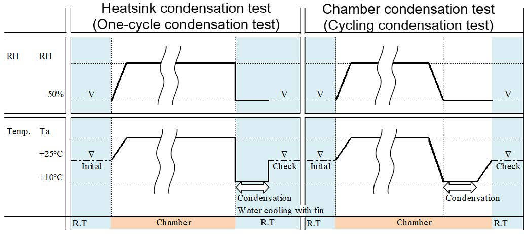
Figure 6: New test sequence for cycling condensation test
Latest high voltage IGBT module technologies
During the humidity investigation of the existing power modules the most sensitive design components were identified. The big influence on the device robustness against humidity had the selection of the proper silicone gel and the design of the chip passivation structure (guard-ring). Especially the passivation structure improvement leads to an enhancements of the device robustness against humidity. The invented by Mitsubishi Electric surface charge control (SCC) technology of the passivation area is the key factor to improve power device durability. It contains a semi-insulation layer above the Si guard ring structure as shown in figure 7.
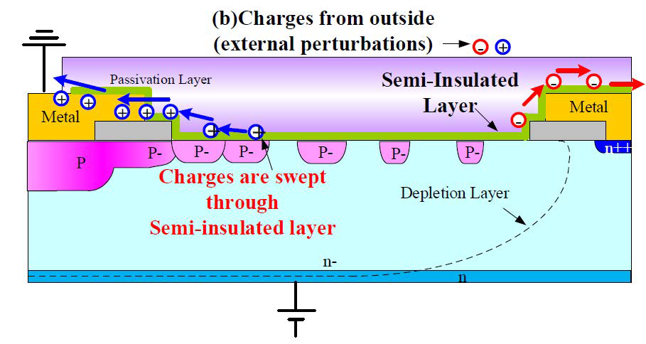
Figure 7: Surface charge control technology
This semi-insulation layer avoids the accumulation of surface charges [6]. The latest X-Series high voltage power modules from Mitsubishi Electric use the SCC - technology.
The X-Series power device capability against condensation was tested using the above described cycling condensation test and compared to the conventional module. When evaluating the conventional module an acceleration factor of 80 was found between 85°C/85%RH and 36°C/95%RH. When comparing the new X-series with conventional design at 85°C/85%RH an improvement by more than 100 times was confirmed by testing. From these test results an unprecedented robustness against 8000 condensation events under IEC 60721-3-5 5K2 reference conditions can be derived for the new X-series, see Fig.8
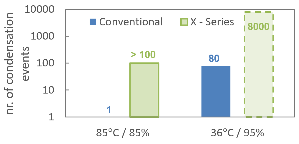
Figure 8: X-Series technology against humidity and condensation in comparison to the conventional product
Conclusion
With the latest X-Series high voltage IGBT modules the device capability could be improved against the humidity and condensation. Also the basic approach to define the life time model for the humidity is established providing to the user the confidence of the proper inverter operation. On the other hand the upcoming SiC technology is still challenging especially considering the smaller structures and new materials. The lessons learned in the past with Si IGBT can be partially utilized and used also for SiC high voltage power modules in the future.
References
[1] Dustin Selvey, “Overview of the Unique Requirements and Challenges for Power Electronics in Mining Equipment” APEC, Long Beach, California, 2016.
[2] Y. Kitajima et al., “Lifetime Estimation Model of HVIGBT Considering Humidity,” PCIM Europe 2017, Nuremberg, Germany, 2017.
[3] C. Zorn and N. Kaminski, “Temperature Humidity Bias (THB) Testing on IGBT Modules at High Bias Levels,” CIPS 2014; Nuremberg, Germany, 2014.
[4] N. Tanaka, “Robust IVIGBT module design against high humidity”, PCIM 2015.
[5] K. Nakamura, “The test method to confirm robustness against condensation”, EPE 2019.
[6] S. Honda, T. Harada, A. Nishii, Z. Chen and K. Shimizu, “High voltage device edge termination for wide temperature range plus humidity with surface charge control (SCC) technology,” ISPSD 2016, Prague, 2016.
Related posts
Now available – DC/DC converters from PREMIUM
We introduced a novelty to our permanent offer in DACPOL in the category of power supplies and converters and today...
Read more
New release in DACPOL lighting for lathes – Kira covers
We introduce a new product into the DACPOL category of industrial lighting and today we offer KIRA covers for...
Read more
Leave a comment