-
-
-
Category
-
Semiconductors
- Diodes
- Thyristors
-
Electro-insulated Modules
- Electro-insulated Modules | VISHAY (IR)
- Electro-insulated Modules | INFINEON (EUPEC)
- Electro-insulated Modules | Semikron
- Electro-insulated Modules | POWEREX
- Electro-insulated Modules | IXYS
- Electro-insulated Modules | POSEICO
- Electro-insulated Modules | ABB
- Electro-insulated Modules | TECHSEM
- Go to the subcategory
- Bridge Rectifiers
-
Transistors
- Transistors | GeneSiC
- SiC MOSFET Modules | Mitsubishi
- SiC MOSFET Modules | STARPOWER
- Module SiC MOSFET ABB’s
- IGBT Modules | MITSUBISHI
- Transistor Modules | MITSUBISHI
- MOSFET Modules | MITSUBISHI
- Transistor Modules | ABB
- IGBT Modules | POWEREX
- IGBT Modules | INFINEON (EUPEC)
- Silicon Carbide (SiC) semiconductor elements
- Go to the subcategory
- Gate Drivers
- Power Blocks
- Go to the subcategory
- Electrical Transducers
-
Passive components (capacitors, resistors, fuses, filters)
- Resistors
-
Fuses
- Miniature Fuses for electronic circuits - ABC & AGC Series
- Tubular Fast-acting Fuses
- Time-delay Fuse Links with GL/GG & AM characteristics
- Ultrafast Fuse Links
- Fast-acting Fuses (British & American standard)
- Fast-acting Fuses (European standard)
- Traction Fuses
- High-voltage Fuse Links
- Go to the subcategory
- Capacitors
- EMI Filters
- Supercapacitors
- Power surge protection
- Go to the subcategory
-
Relays and Contactors
- Relays and Contactors - Theory
- 3-Phase AC Semiconductor Relays
- DC Semiconductor Relays
- Controllers, Control Systems and Accessories
- Soft Starters and Reversible Relays
- Electromechanical Relays
- Contactors
- Rotary Switches
-
Single-Phase AC Semiconductor Relays
- AC ONE PHASE RELAYS 1 series| D2425 | D2450
- One phase semiconductor AC relays CWA and CWD series
- One phase semiconductor AC relays CMRA and CMRD series
- One phase semiconductor AC relays - PS series
- Double and quadruple semiconductor AC relays - D24 D, TD24 Q, H12D48 D series
- One phase semiconductor relays - gn series
- Ckr series single phase solid state relays
- One phase AC semiconductor relays for DIN bus - ERDA I ERAA series
- 150A AC single phase relays
- Rail Mountable Solid State Relays With Integrated Heat Sink - ENDA, ERDA1 / ERAA1 series
- Go to the subcategory
- Single-Phase AC Semiconductor Relays for PCBs
- Interface Relays
- Go to the subcategory
- Cores and Other Inductive Components
- Heatsinks, Varistors, Thermal Protection
- Fans
- Air Conditioning, Accessories for Electrical Cabinets, Coolers
-
Batteries, Chargers, Buffer Power Supplies and Inverters
- Batteries, Chargers - Theoretical Description
- Modular Li-ion Battery Building Blocks, Custom Batteries, BMS
- Batteries
- Battery Chargers and Accessories
- Uninterruptible Power Supply and Buffer Power Supplies
- Inverters and Photovoltaic Equipments
- Energy storage
- Fuel cells
- Lithium-ion batteries
- Go to the subcategory
-
Automatics
- Futaba Drone Parts
- Limit Switches, Microswitches
- Sensors, Transducers
-
Infrared Thermometers (Pyrometers)
- IR-TE Series - Water-proof Palm-sized Radiation Thermometer
- IR-TA Series - Handheld Type Radiation Thermometer
- IR-H Series - Handheld Type Radiation Thermometer
- IR-BA Series - High-speed Compact Radiation Thermometer
- IR-FA Series - Fiber Optic Radiation Thermometer
- IR-BZ Series - Compact Infrared Thermometers
- Go to the subcategory
- Counters, Time Relays, Panel Meters
- Industrial Protection Devices
- Light and Sound Signalling
- Thermographic Camera
- LED Displays
- Control Equipments
-
Recorders
- Hybrid Recorders - AL3000 Series | CHINO
- Graphic Recorder - KR2000 Series | CHINO
- Ubiquitous Recorders - KR5000 Series | CHINO
- Palm-sized Temperature/Humidity Meters - HN-CH Series | CHINO
- Consumables for Recorders
- 71VR1 - Compact Paperless Recorder | M-SYSTEM
- Graphic Recorder - KR3000 Series | CHINO
- PC Recorders - R1M Series | M-SYSTEM
- PC Recorders - R2M Series | M-SYSTEM
- PC Recorders - RZMS Series | M-SYSTEM
- PC Recorders - RZUS Series | M-SYSTEM
- Go to the subcategory
- Go to the subcategory
-
Cables, Litz wires, Conduits, Flexible connections
- Wires
- Litz wires
- Cables for extreme applications
- Sleevings
-
Braids
- Flat Braids
- Round Braids
- Very Flexible Flat Braids
- Very Flexible Round Braids
- Cylindrical Cooper Braids
- Cylindrical Cooper Braids and Sleevings
- Flexible Earthing Connections
- Galvanized and Stainless Steel Cylindrical Braids
- PCV Insulated Copper Braids (temp. up to 85C)
- Flat Aluminium Braids
- Junction Set - Braids and Tubes
- Go to the subcategory
- Traction Equipment
- Cable Terminals
- Flexible Insulated Busbars
- Flexible Multilayer Busbars
- Cable Duct Systems
- Hoses
- Go to the subcategory
- View all categories
-
Semiconductors
-
-


Parallel Operation: Influence of Power Module Parameters

Table of contents
Parallel Operation: Influence of Power Module Parameters
The challenge of IGBT module paralleling is to understand the necessary de-rating of power converters under consideration of different module parameters. This understanding is important for proper module parallel operation inside the thermal and safe operation limits. This article describes the methodology of how to analyze the influence of module parameters on current sharing and switching energy imbalance for parallel operation of power modules.
By N. Soltau, E. Wiesner, Mitsubishi Electric Europe B.V., Ratingen, Germany Y. Ando, J. Sakai, K. Hatori, Mitsubishi Electric Corporation, Fukuoka, Japan
Introduction
The current imbalance during module operation can be caused both by the characteristics of the paralleled power modules, such as the different forward voltage and by the design of the power converter itself. The interface of power modules, such as power connection on DC and AC side, the design of gate driver, and the gate driver connection to the power modules, have an influence on static and dynamic current imbalance of modules connected in parallel. An overview of the various factors that influence the performance of the power modules connected in parallel is shown in figure 1.
In the chapters below, the focus is on the analysis of the IGBT and diode characteristics with regard to current imbalance in parallelconnected power modules. For the following analysis, uniform cooling conditions are considered.
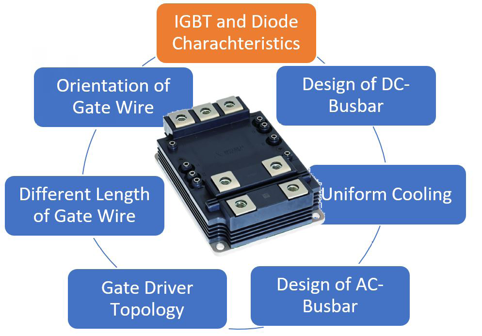
Figure 1: Factors affecting the performance of power modules connected in parallel
Evaluation Setup and Test Sample
Each rolling stock manufacturer has its own unique converter design, so it would be difficult for semiconductor manufacturers to make representative power module analysis without standardized test setup. This difficulty was discussed in Horizon 2020 Project “Shift2Rail” [2]. The project members agreed to define a standardized interface between semiconductor supplier and power converter manufacturer to discuss de-rating for power modules. The reference setup is shown in figure 2. One of the goals for reference setup is to reduce the influence of external components on the current imbalance of parallel connected power modules as much as possible.
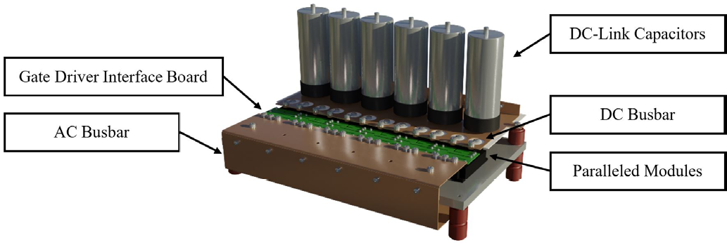
Figure 2: Reference test setup for paralleling evaluation
On the DC side, each power module has an individual DClink capacitor; the AC power connection is made via a wide busbar with a central load connection under the modules. Only one central gate driver is used in combination with a low-inductive interface board to control the paralleled modules.
The reference test setup was chosen for investigation of module parallel connection in the following chapters. CM450DA-66X module in the LV100 package is a representative X-Series power module that was selected as device under test for performing the evaluation and analysis. The X-Series line-up with silicon chipset and aluminum base plate is shown in table 1. These power modules feature the latest X-Series 7th Gen. cutting edge chip set with CSTBT™(III) trench IGBT and RFC diode. Both IGBT and diode chips have a positive temperature coefficient for forward voltage over a wide current range. This feature is beneficial for thermal balancing between the parallel connected modules during operation if the temperature is not evenly distributed across the heatsink. The NTC temperature sensor, which is integrated into the module, allows the monitoring of case temperature for each individual parallel connected module.
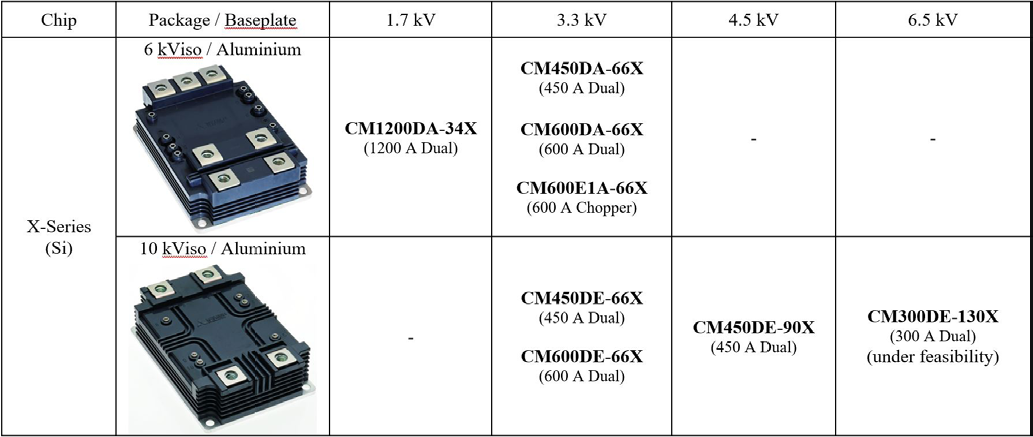
Table 1: LV/HV100 X-Series line-up
In addition, the dual-power modules of the X-series use a new innovative aluminum base plate with integrated AlN ceramic insulation, the so-called MCB (Metal Casting direct Bonding) baseplate. The new baseplate structure has a significantly smaller junction to case thermal resistance compared to conventional structure, which allows output-power increase or reduction of the operating junction temperature. In addition, Mitsubishi Electric’s X-Series power modules offer features for demanding railway application such as high CTI value of housing material, partial discharge measurement, high quality control and traceability.
Correlation of Power-Module Parameters and Parallel-Switching Waveforms
To investigate the impact of different IGBT power module parameters on the current sharing, parallel connections of ten different pairs of power modules have been measured. Afterwards, linear regression analysis is performed to correlate characteristics of switching waveforms and power-module parameters. Please find more information in [3].
The devices under test are 3.3 kV / 450 A (CM450DA-66X) power modules in the LV100 package. These devices show a natural distribution in their electrical parameters. Hence, collector-emitter saturation voltage ranges from 2.61 V to 2.81 V, gate-emitter threshold voltage ranges from 6.56 V to 7.70 V, and diode forward voltage ranges from 2.20 V to 2.45 V. The ten pairs have been analyzed in terms of their switching characteristics during turn-on, turn-off and reverse recovery.
Turn-Off Switching Analysis
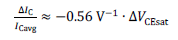
Figure 3 shows two exemplary turn-off measurement results. When IGBT device parameters are similar, nice current sharing can be achieved. On the contrary, in case of different power module parameters, the load current unequally shares between power modules.
With linear regression analysis of the ten pairs, the correlation between IGBT power module parameters and switching characteristics is determined. It is found that the difference in steady state current ΔIC correlates with the difference in collector-emitter voltage only. Other power module parameters are found to be insignificant (determination coefficient < 95%). Linear regression analysis leads the following relationship for the current imbalance. Please refer to [3] for further details.
Turn-On Switching Analysis
Figure 4 shows turn-on switching waveforms with two power modules connected in parallel. If power module parameters are similar, the current will share equally between both power modules. However, when power modules are different, unequal current sharing between power modules is to be expected.
It is found that current sharing correlates with gate-emitter threshold voltage difference ΔVGE(th) and difference in forward voltage of the complementary free-wheel diodes ΔVEC. Linear regression analysis leads the following relationship for the current imbalance. Please refer to [3] for further details.
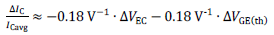
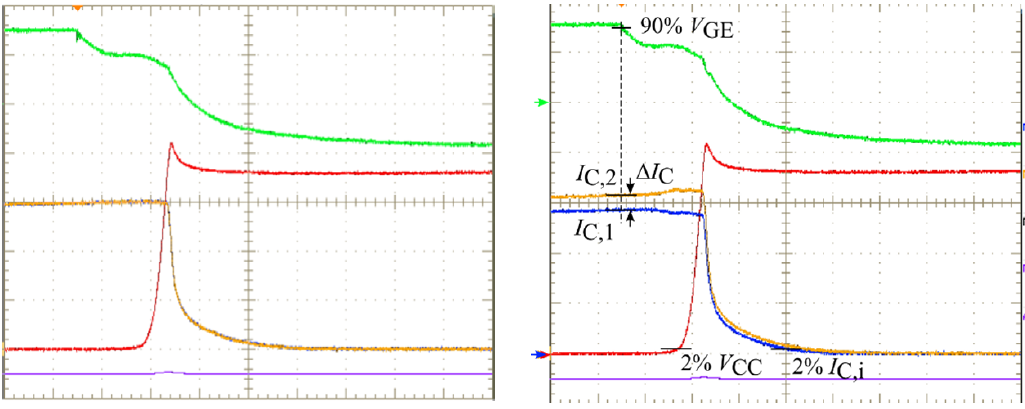
Figure 3: Exemplary turn-off waveforms (green: VGE 10V/div, blue: IC1 150A/div, yellow: IC2 150A/div, red: VCE 500V/div, 2.0 us/div)
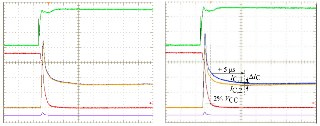
Figure 4: Exemplary turn-on waveforms (green: VGE 10V/div, blue: IC1 300A/div, yellow: IC2 300A/div, red: VCE 500V/div, 2.0 us/div)
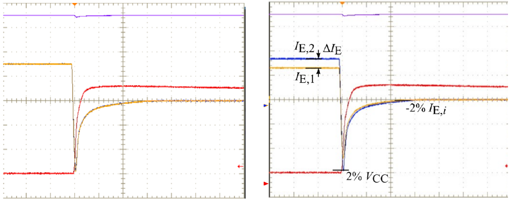
Figure 5: Exemplary reverse-recovery waveforms (blue: IC1 300A/div, yellow: IC2 300A/div, red: VCE 500V/div, 2.0 us/div)
Diode Reverse-Recovery Switching
Exemplary switching results of diode reverse recovery are shown in figure 5. Again, the current shares equally between two power modules if the power-module parameters are different, differences in the static current and in the peak reverse recovery current becomes visible.
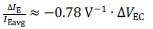
Linear regression analysis shows that the static current sharing correlates solely on difference of diode forward voltage ΔVEC. Other power-module parameters are found to be insignificant. The following relationship for the current imbalance is found. Please refer to [3] for further details.
De-rating Calculation up to Six-Times Paralleling
Based on derating factors for currents and energies, that were derived in previous chapter, the required derating in case of parallel connection of more than two modules can be defined. For this, it will be assumed that one of the paralleled modules has a minimum characteristic (resulting in maximum switching energy or current) while all other modules have the maximum characteristics (leading to minimum switching energy or current). By using the following equation, the derating ratio for the collector current for more than two parallel connected modules can be calculated as an example.

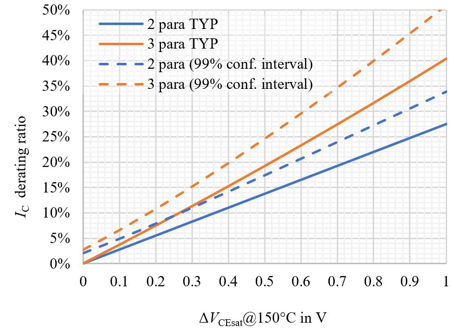
Figure 6: Collector current derating ratio versus forward voltage difference
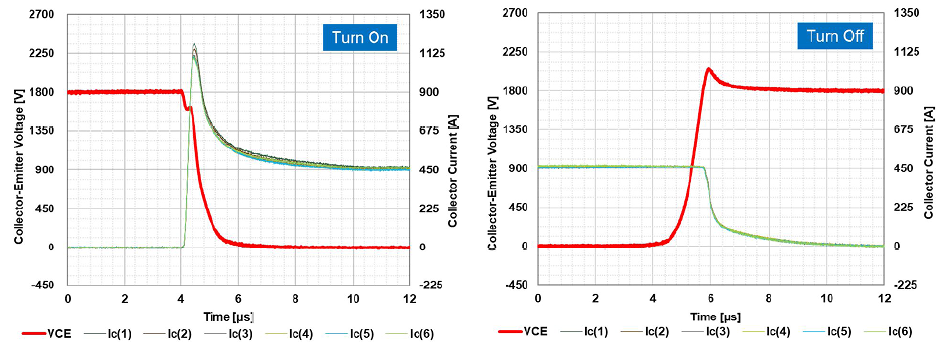
Figure 7: Switching waveforms for 6-times parallel connection (conditions: VCC = 1800V, IC = 2700A (450A per device), Tj = 150°C, VGE = +15V / -9V, RG(on) = 2.7Ω, RG(off) = 62Ω, CGE = 33nF)
The parameter n is the number of parallel connected modules. The parameter x is the identified imbalance ratio from the measurement of two parallel connected modules (for example (ΔIC/ICavg according to (1) and (2) or (ΔIE/IEavg according to (3)). As a result, the de-rating dependency on the grouping parameter can be defined as shown in figure 6. The figure already illustrates that confidence intervals, as determined by the regression analysis, become also very helpful regarding the derating ratio of multiple power modules.
The previous analysis shows that if small parameter variation is guaranteed, a small derating ratio and good current sharing is achievable. This is demonstrated by figure 7. It shows switching type test results of a 6-times parallel connection. The current homogenously shares among the six power modules which leads to good balance of losses and optimal utilization of available chip area.
Conclusion
This article explains a methodology to investigate the influence of power-module parameters on the switching characteristics of a parallel connection. For each switching type, IGBT turn-off, turn-on and diode reverse recovery, the influence of the different device parameters is investigated. Considering only the significant parameters, a model is provided to calculate differences in switching characteristics on arbitrary device parameters. It is shown how the results are transferred to parallel connection with more than two devices. Finally, homogeneous current sharing between six devices in a parallel connection is confirmed. The switching waveforms proof that with welldesigned converter layout and well-paired LV100 modules ideal current sharing is achieved.
References
[1] T. Wiik, „D1.2, New generation power semiconductor, Common specification for traction and market analysis, technology roadmap, and value cost prediction,“ Roll2Rail , H2020 - 636032, 2016.
[2] A. Nagel, J. Weigel, et. al., „Paralleling reference setup,“ Shift2Rail, Pinta, H2020 - 730668, 2019.
[3] Y. Ando, J. Sakai, K. Hatori, N. Soltau and E. Wiesner, “Influence of IGBT and Diode Parameters on the Current Sharing and Switching-Waveform Characteristics of Parallel-Connected Power Modules,” 2022 24th European Conference on Power Electronics and Applications (EPE’22 ECCE Europe), 2022, pp. 1-11.
Related posts
Now available – DC/DC converters from PREMIUM
We introduced a novelty to our permanent offer in DACPOL in the category of power supplies and converters and today...
Read more
New release in DACPOL lighting for lathes – Kira covers
We introduce a new product into the DACPOL category of industrial lighting and today we offer KIRA covers for...
Read more
Leave a comment