-
BackX
-
Components
-
-
Category
-
Semiconductors
- Diodes
- Thyristors
-
Electro-insulated Modules
- Electro-insulated Modules | VISHAY (IR)
- Electro-insulated Modules | INFINEON (EUPEC)
- Electro-insulated Modules | Semikron
- Electro-insulated Modules | POWEREX
- Electro-insulated Modules | IXYS
- Electro-insulated Modules | POSEICO
- Electro-insulated Modules | ABB
- Electro-insulated Modules | TECHSEM
- Go to the subcategory
- Bridge Rectifiers
-
Transistors
- Transistors | GeneSiC
- SiC MOSFET Modules | Mitsubishi
- SiC MOSFET Modules | STARPOWER
- Module SiC MOSFET ABB’s
- IGBT Modules | MITSUBISHI
- Transistor Modules | MITSUBISHI
- MOSFET Modules | MITSUBISHI
- Transistor Modules | ABB
- IGBT Modules | POWEREX
- IGBT Modules | INFINEON (EUPEC)
- Silicon Carbide (SiC) semiconductor elements
- Go to the subcategory
- Gate Drivers
- Power Blocks
- Go to the subcategory
- Electrical Transducers
-
Passive components (capacitors, resistors, fuses, filters)
- Resistors
-
Fuses
- Miniature Fuses for electronic circuits - ABC & AGC Series
- Tubular Fast-acting Fuses
- Time-delay Fuse Links with GL/GG & AM characteristics
- Ultrafast Fuse Links
- Fast-acting Fuses (British & American standard)
- Fast-acting Fuses (European standard)
- Traction Fuses
- High-voltage Fuse Links
- Go to the subcategory
- Capacitors
- EMI Filters
- Supercapacitors
- Power surge protection
- Go to the subcategory
-
Relays and Contactors
- Relays and Contactors - Theory
- 3-Phase AC Semiconductor Relays
- DC Semiconductor Relays
- Controllers, Control Systems and Accessories
- Soft Starters and Reversible Relays
- Electromechanical Relays
- Contactors
- Rotary Switches
-
Single-Phase AC Semiconductor Relays
- AC ONE PHASE RELAYS 1 series| D2425 | D2450
- One phase semiconductor AC relays CWA and CWD series
- One phase semiconductor AC relays CMRA and CMRD series
- One phase semiconductor AC relays - PS series
- Double and quadruple semiconductor AC relays - D24 D, TD24 Q, H12D48 D series
- One phase semiconductor relays - gn series
- Ckr series single phase solid state relays
- One phase AC semiconductor relays for DIN bus - ERDA I ERAA series
- 150A AC single phase relays
- Rail Mountable Solid State Relays With Integrated Heat Sink - ENDA, ERDA1 / ERAA1 series
- Go to the subcategory
- Single-Phase AC Semiconductor Relays for PCBs
- Interface Relays
- Go to the subcategory
- Cores and Other Inductive Components
- Heatsinks, Varistors, Thermal Protection
- Fans
- Air Conditioning, Accessories for Electrical Cabinets, Coolers
-
Batteries, Chargers, Buffer Power Supplies and Inverters
- Batteries, Chargers - Theoretical Description
- Modular Li-ion Battery Building Blocks, Custom Batteries, BMS
- Batteries
- Battery Chargers and Accessories
- Uninterruptible Power Supply and Buffer Power Supplies
- Inverters and Photovoltaic Equipments
- Energy storage
- Fuel cells
- Lithium-ion batteries
- Go to the subcategory
-
Automatics
- Futaba Drone Parts
- Limit Switches, Microswitches
- Sensors, Transducers
-
Infrared Thermometers (Pyrometers)
- IR-TE Series - Water-proof Palm-sized Radiation Thermometer
- IR-TA Series - Handheld Type Radiation Thermometer
- IR-H Series - Handheld Type Radiation Thermometer
- IR-BA Series - High-speed Compact Radiation Thermometer
- IR-FA Series - Fiber Optic Radiation Thermometer
- IR-BZ Series - Compact Infrared Thermometers
- Go to the subcategory
- Counters, Time Relays, Panel Meters
- Industrial Protection Devices
- Light and Sound Signalling
- Thermographic Camera
- LED Displays
- Control Equipments
-
Recorders
- Hybrid Recorders - AL3000 Series | CHINO
- Graphic Recorder - KR2000 Series | CHINO
- Ubiquitous Recorders - KR5000 Series | CHINO
- Palm-sized Temperature/Humidity Meters - HN-CH Series | CHINO
- Consumables for Recorders
- 71VR1 - Compact Paperless Recorder | M-SYSTEM
- Graphic Recorder - KR3000 Series | CHINO
- PC Recorders - R1M Series | M-SYSTEM
- PC Recorders - R2M Series | M-SYSTEM
- PC Recorders - RZMS Series | M-SYSTEM
- PC Recorders - RZUS Series | M-SYSTEM
- Go to the subcategory
- Go to the subcategory
-
Cables, Litz wires, Conduits, Flexible connections
- Wires
- Litz wires
- Cables for extreme applications
- Sleevings
-
Braids
- Flat Braids
- Round Braids
- Very Flexible Flat Braids
- Very Flexible Round Braids
- Cylindrical Cooper Braids
- Cylindrical Cooper Braids and Sleevings
- Flexible Earthing Connections
- Galvanized and Stainless Steel Cylindrical Braids
- PCV Insulated Copper Braids (temp. up to 85C)
- Flat Aluminium Braids
- Junction Set - Braids and Tubes
- Go to the subcategory
- Traction Equipment
- Cable Terminals
- Flexible Insulated Busbars
- Flexible Multilayer Busbars
- Cable Duct Systems
- Hoses
- Go to the subcategory
- View all categories
-
Semiconductors
-
-
- Suppliers
-
Applications
- CNC Machine Tools
- DC and AC Drives (Inverters)
- Energetics
- Energy bank
- Equipment and Components for Hazardous Areas [Ex]
- Equipment for Distribution, Control and Telecommunications Cabinets
- HVAC Automation
- Induction Heating
- Industrial Automation
- Industrial Protective Devices
- Machines for Drying and Wood Processing
- Machines for Thermoforming Plastics
- Mining, Metallurgy and Foundry
- Motors and Transformers
- Power Supplies (UPS) and Rectifier Systems
- Printing
- Temperature Measurement and Regulation
- Test and Laboratory Measurements
- Tram and Railway Traction
- Welding Machines
-
Assembly
-
-
Inductors
-
-
Induction devices
-
-
https://www.dacpol.eu/pl/naprawy-i-modernizacje
-
-
Service
-
- Contact
- Zobacz wszystkie kategorie
Small Power IPM for High Integration Demand

Small Power IPM for High Integration Demand
Since the first introduction of the DIPIPM™ (Transfer molded type intelligent power module) product family in 1997, these products have been continuously improved and further developed. In the meantime, seven DIPIPM™ product groups have been created in different housing designs, current and voltage classes.
By E. Stumpf, E. Wiesner, Mitsubishi Electric Europe B.V., Ratingen, Germany A. Goto, Mitsubishi Electric Corporation, Fukuoka, Japan
Introduction
A wide motor power range up to 15 kW for different motor voltages is covered by the DIPIPM™ product family. These products are now used in numerous applications such as servo and standard drives, air conditioning systems, refrigerators, fans and washing machines.
A unique feature of these products is the high degree of integration of functions with numerous control and protective measures, such as under-voltage protection, over-temperature detection and short circuit protection.
As the number of household appliances increases, so does the need for cost-effective and integrated solutions. Customers want to utilize the recent chip developments in their products as quickly as possible and bring them to market to benefit from the increased efficiency and cost advantages. In addition, these products with the high integration of functions offer better reliability compared to discrete solutions. The SLIMDIP™ product group is the best choice to achieve the above customer targets.
SLIMDIP™ Products Line-up and Features
The SLIMDIP™ product group, introduced in 2015 [1], has recently enjoyed particular popularity. Due to this fact, Mitsubishi Electric is developing further products in the same package with additional current ratings.
In addition to the already presented SLIMDIP-S (5 A), SLIMDIP-L (15 A regular frequency) and SLIMDIP-W (15 A high frequency), next additional products are coming onto the market. It is the SLIMDIP-M with a 10 A current rating for high switching frequencies. Further current ratings are under development already.
The common SLIMDIP™ product features are:
- control input interface compatibility to 5 V and 3 V
- high isolation voltage of 2000 Vrms, one minute
- integrated bootstrap circuit with diodes and current limiting resistors for the P-side power supply
- integrated under-voltage protection
- extended over-temperature protection with additional LVIC temperature monitoring
- integrated short-circuit and over-current protection
| Product name | Ratings | Switching speed | |
|---|---|---|---|
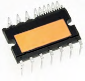 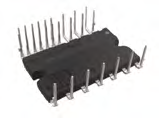 18.8 mm x 32.8 mm |
SLIMDIP-S | 5 A, 600 V | Fast |
| SLIMDIP-M | 10 A, 600 V | Fast | |
| SLIMDIP-L | 15 A, 600 V | Regular | |
| SLIMDIP-W | 15 A, 600 V | Fast | |
| Under development | Higher current ratings |
Table 1: Line-up of SLIMDIP™ IPM product group
For a better performance understanding of each device, the diagram in figure 1 shows the simulated output current versus switching frequency.

Figure 1: SLIMDIP™ products output current simulation results
The SLIMDIP™ products use the 2nd Gen. reverse conducting IGBT chips (RC-IGBTs). With this technology, a further significant step towards high integration with more compact and more straightforward solutions can be achieved.
RC-IGBT Power Chip used in SLIMDIP™ IPM
Both structures, IGBT and free-wheeling diode are integrated into one chip in an RC-IGBT chip. Especially for small current devices, it contributes remarkably to the package downsizing and system cost reduction. The wire bond layout is easier to realize than the conventional solution with separate IGBT and diode [2].
The particular difficulty with the RC-IGBT is that it is challenging to optimize the balance between IGBT and diode performance. For this, Mitsubishi Electric investigated different design concepts to improve the reverse recovery characteristics of diode and total RC-IGBT chip performance. Based on this study, the second generation of the RCIGBT was released.
Mitsubishi Electric uses the 2nd Gen. RC-IGBT in SLIMDIP™ products. The 2nd Gen. RC-IGBT structure is shown schematically in figure 3 below.
The diode VEC vs. ERR trade-off relationship was improved by approximately 52 % in the second generation of RC-IGBT chip without decreasing the IGBT performance. This improvement was achieved especially by advanced thin wafer technology and optimized diode IGBT layout on the chip with properly selected diode structure and diode ratio.

Figure 2: 2nd Gen. RC-IGBT chip structure
Integrated Over-Temperature Protection
An essential feature of the SLIMDIP™ family is comprehensive temperature monitoring. In addition to the hardware-implemented overtemperature shutdown (OT) function, it is possible to continuously monitor the temperature during operation (VOT) and react accordingly before the hardware shutdown occurs.
The excess temperature shutdown is at 130 °C typically. As soon as this temperature is reached at the LVIC, the IPM switches off its gate outputs and reports an excess temperature error to the microcontroller.
With additional analog temperature monitoring on the LVIC, irregularities in the cooling, such as fan defects or heavy pollution, can be determined at an early stage. The IPM user has different options to utilize the temperature monitoring function (VOT). There is a possibility to output an error message or change the control scheme before the IPM reaches the over-temperature trip level and switches the gates off.
IPM Power Supply Integrity
Another beneficial feature of the SLIMDIP™ family is the utilization of high voltage IC (HVIC) with the required components like a bootstrap diode (BSD) and current limiting resistors. The standard three-phase inverter requires four isolated power supplies; three for P-Side and one for N-Side. Integrated into the SLIMDIP™ HVIC circuit allows reducing the number of power supplies from four to one. [3] The usual external functional isolation of P-Side switches is not required. This functional isolation is provided inside of HVIC via level shifting.
Figure 3 shows the principle diagram schematically for a bootstrap circuit.

Figure 3: Bootstrap circuit
The SLIMDIP™ LVIC has to be supplied with a sufficient power supply voltage of 15 V. This voltage secures the proper functionality of the N-side switches and charging of the P-Side. When the output (U, V, W) potential goes down to the GND level, the current flows through the bootstrap diode and charges the bootstrap capacitor. When output (U, V, W) voltage returns to VCC, the bootstrap capacitor's low side remains connected to the emitter of the P-Side switch.
The capacitor discharges its energy driving the P-Side switch's gate to a voltage sufficient to turn it on, while the bootstrap diode blocks that voltage from leaking back.
All SLIMDIP™ power modules are equipped with HVIC, bootstrap diodes and with in-rush current limited resistances. The built-in components reduce the assembly cost and system FIT rates during operation.
Short Circuit Protection Function
A further feature in SLIMDIP™ is detecting short circuit SC current and stopping the operation of IPM. SLIMDIP™ uses an external shunt resistor for the short current detection, as pictured in figure 4. The protection circuit is realized in the LVIC. The voltage over shunt resistance is compared with reference SC trip voltage inside LVIC to detect high short circuit current. The threshold voltage trip level is typically 0.48 V. The exceeding of reference trip voltage would automatically trigger protection function. All gate signals of bottom switches would be interrupted, and a fault output signal would be generated. The external RC filter is to be used to avoid activation of protection by normal switching noise. A time constant of about two μs recommended being used for the RC filter. Additionally, it is recommended to use shunt resistance and pattern wiring with low effective inductance to prevent error fault output.

Figure 4: Short circuit detection principle for SLIMDIP™ IPM
Conclusion
SLIMDIP™ products become the worldwide standard solution for power electronic systems with requirements on a high degree of integration, performance and reliability. The power module SLIMDIP-M with 10 A and 600 V rating was developed to expand the product lineup. The development of the SLIMDIP™ IPM with even higher power density is already started to cover the future demand and continue the SLIMDIP™ product family's success.
References
[1] S. Shibata, M. Kato and H. Zhang, "New Transfer-Molded SLIMDIP for white goods using thin RC-IGBT with a CSTBTTM structure," Proceedings of PCIM Europe 2015; International Exhibition and Conference for Power Electronics, Intelligent Motion, Renewable Energy and Energy Management, Nuremberg, Germany, 2015, pp. 1-6.
[2] T. Yoshida, T. Takahashi, K. Suzuki, and M. Tarutani, “The second-generation 600V RC-IGBT with optimized FWD,” in 2016 28th International Symposium on Power Semiconductor Devices and ICs (ISPSD), Prague, Czech Republic, 62016, pp. 159–162.
[3] Mitsubishi Electric, Bootstrap Circuit Design Manual. [Online]. Available: https://www.mitsubishielectric.com/semiconductors/ files/manuals/dipipm_bootstrap_circuit_ e.pdf (accessed: Feb. 2021).
Related posts
 Now available – DC/DC converters from PREMIUM
 New release in DACPOL lighting for lathes – Kira covers

Leave a comment