Tester for calibrating relays RT2, RT3
Construction and operation
The tester consists of a sinusoidal current source with adjustable amplitude within the range of 10 A to 500 A and a measuring path enabling simultaneous testing of up to 1 piece of three-track apparatus. Functionally, the measurement path consists of contactors for current ranges 50 A, 100 A, 250 A, 500 A and LEM transducers for current measurement.
The test stand consists of a computer equipped with a control and measurement card. Messages displayed on the screen are presented in text form, making it easy to operate the tester. During work, the computer provides visualisation of the test course.
The test stand is operated by switching on the tester's power supply and then, using a computer, selecting the type of apparatus to be tested and placing it in the socket. The test starts when the sliding door is closed. The end of the test causes automatic blocking of the test current source and unlocking of the door.
The test stand consists of a measuring track, a sinusoidal current source in a metal enclosure (cabinet) on wheels with locks, equipped with a rear door, on which the operator's desk and tabletop are placed. The desktop consists of a monitor screen, keyboard, mouse, control buttons and indicator lights.
The software allows:
- performing tests required by standards (constant values of rated current multiplication factor);
- the same tests with manually entered rated current multiples (constructional test);
- visualization of the examination process;
- archiving of results.
Technical data
| Tested relays |
RT2, RT3 |
| Maximum number of simultaneously tested relays |
1 pcs. |
| Number of test sockets |
2 pcs. |
| Power supply |
230 V; 50 Hz |
| Power supply tolerance |
+10% ÷ -5% |
| Maximum current drawn from the mains |
≤ 8,5 A |
| Output power |
2 kW |
| Test current |
sine 50 Hz |
| Total distortion |
≤ 5% |
| Test current adjustment range |
10÷500 A |
| Method of current regulation |
stepped in 4 ranges and smooth within each range |
| RMS stabilization |
1,5% |
| Operation mode |
24 h/day |
| Environmental conditions |
operating temperature: 10 °C ÷ 35 °C
humidity: 10% ÷ 75% |
| Current source housing |
cabinet made of aluminium profiles on castors with locks |
| Dimensions of the current source cabinet (H x W x D) |
1190 x 1000 x 1400 [mm] |
| Tested instruments RT2 and RT3 |
 |
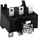 |


