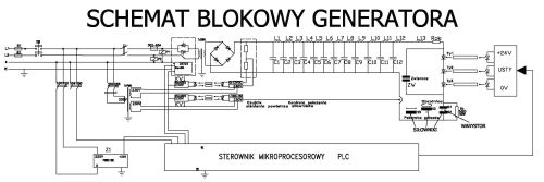
Square shock generator is designed to test energy strength of low and medium voltage varistors according to PN-IEC 99-4 standard. Tests are performed during the production process on all the varistors. The generator consists of: capacitor bank with coils, thyristor attachment, WN loader, measurement system, control and automation system, control panel. The HV circuit of the generator and its control and automatic systems as well as the measuring systems are isolated from the casing and are not connected to "the earth". The generator is placed in metal housing equipped with wheels with blockade. The operator station is completely isolated from the generator's circuits and does not require any additional means of shock protection.
Generator parameters
supply voltage - 400 VAC;
rated voltage of the generator - 15 kVDC;
classification voltage of the highest tested varistor - 6000 VDC;
maximum continuous operating voltage of the tested varistor - 3400V RMS;
classification voltage of the lowest tested varistor - 200 VDC;
continuous operating voltage of the lowest tested varistor - 120 VRMS;
rectangular surge, peak value - 600 A;
duration of surge - 2000 s;
frequency of surge - co 5 s.
Technical data
Generator HV circuit
- chain line consisting of twelve LC links; - 12.5 kW load capacity 400 V/12500 V transmission, 13.9 A/0.4 A current ratio; - diode rectifier 24 kV, 1.1 A; - thyristor switch 14400 V, 765 A, 300 A/s; - diode radiation control via fiber optic links;
Control and automation system
- PLC that manages the entire generator; - microprocessor-based loader controller; - microprocessor controllers specialized for measurement of surge current and charging voltage of capacitor banks; - transmission of signals in RS485 standard through converters and fiber optic links;
Surge current measuring system
- measurement on HV side through Hall-effect transducer and specialized microprocessor system; - transmission of signals through bidirectional fiber optic links in RS485 standard; - power supply via HV transformer; - view the shape and parameters of the test stroke on the monitor of a computer connected to the RS485 socket;
System for measuring the voltage of capacitor banks
- measurement on HV side through a resistance voltage divider and a specialized microprocessor system; - transmission of signals through bidirectional fiber optic links in RS485 standard; - power supply via HV transformer;
Operating console
- PLC console (text messages displayed to facilitate the operator's work); - set operating parameters with the possibility to view them during operation; - the generator stage that is currently running; - sequence number of the current stroke; - the parameters of the generated surge current; - value of capacitor battery charging voltage; - indicator lights NETWORK ON/OFF, OPERATION, END OF CYCLE, EMERGENCY; - control buttons START, STOP, OFF FAILURE, PREVIEW, RECHARGE; - worktop with a turntable containing two test sockets.
Automation
- pneumatic actuators for the turntable, the test cell cover and its electrodes, and the capacitor bank contactor..