shopping_cart
Carro
0,00 PLN
0
Portapapeles
Debes estar logueado
-
-
-
Category
-
Semiconductores
- Diodos
- Tiristores
-
Módulos con aislamiento eléctrico
- Módulos con aislamiento eléctrico | VISHAY (IR)
- Módulos con aislamiento eléctrico | INFINEON (EUPEC)
- Módulos con aislamiento eléctrico | Semikron
- Módulos con aislamiento eléctrico | POWEREX
- Módulos con aislamiento eléctrico | IXYS
- Módulos con aislamiento eléctrico | POSEICO
- Módulos con aislamiento eléctrico | ABB
- Módulos con aislamiento eléctrico | TECHSEM
- Przejdź do podkategorii
- Rectificadores de puente
-
Transistores
- Transistores | GeneSiC
- Módulos SiC MOSFET | Mitsubishi
- Módulos SiC MOSFET | STARPOWER
- Módulos ABB SiC MOSFET
- Módulos IGBT | MITSUBISHI
- Módulos de transistores | MITSUBISHI
- Módulos MOSFET | MITSUBISHI
- Módulos de transistores | ABB
- Módulos IGBT | POWEREX
- Módulos IGBT | INFINEON (EUPEC)
- Elementos semiconductores de carburo de silicio (SiC)
- Przejdź do podkategorii
- Controladores de puerta
- Bloques de energía
- Przejdź do podkategorii
- Convertidores de corriente y tensión LEM
-
Componentes pasivos (condensadores, resistencias, fusibles, filtros)
- Resistencias
-
Fusibles
- Fusibles miniatura para circuitos electrónicos, serie ABC y AGC
- Fusibles tubulares de acción rápida
- Eslabones fusibles de retardo de tiempo con características GL / GG y AM
- Eslabones fusibles ultrarrápidos
- Fusibles de acción rápida (estándar británico y estadounidense)
- Fusibles de acción rápida (estándar europeo)
- Fusibles de tracción
- Eslabones fusibles de alto voltaje
- Przejdź do podkategorii
-
Condensadores
- Condensadores de motor
- Condensadores electrolíticos
- Condensadores de película
- Condensadores de potencia
- Condensadores para circuitos de CC
- Condensadores de corrección del factor de potencia
- Condensadores de alto voltaje
- Condensadores de calentamiento por inducción
- Condensadores de almacenamiento de energía y pulsos
- Condensadores de ENLACE CC
- Condensadores para circuitos AC/DC
- Przejdź do podkategorii
- Filtros EMI
- Supercondensadores
- Protección contra sobretensiones
- Filtros para detección de emisiones TEMPEST
- Pararrayos
- Przejdź do podkategorii
-
Relés y contactores
- Teoría de relés y contactores
- Relés semiconductores de CA trifásicos
- Relés semiconductores de CA trifásicos
- Reguladores, controles y accesorios
- Arranques suaves y contactores de inversión
- Relés electromecánicos
- Contactores
- Interruptores giratorios
-
Relés semiconductores de CA monofásicos
- Relés semiconductores CA monofásicos, serie 1 | D2425 | D2450
- Relés semiconductores CA monofásicos, series CWA y CWD
- Relés semiconductores CA monofásicos de las series CMRA y CMRD
- Relés semiconductores de CA monofásicos, serie PS
- Relés semiconductores de CA dobles y cuádruples, serie D24 D, TD24 Q, H12D48 D
- Relés de estado sólido monofásicos, serie gn
- Relés semiconductores de ca monofásicos, serie ckr
- Relés AC monofásicos SERIE ERDA Y ERAA para carril DIN
- Relés AC monofásicos para corriente 150A
- Relés dobles de estado sólido integrados con disipador de calor para carril DIN
- Przejdź do podkategorii
- Relés semiconductores CA monofásicos para PCB
- Relés de interfaz
- Przejdź do podkategorii
- Núcleos y otros componentes inductivos
- Radiadores, varistores, protecciones térmicas
- Aficionados
- Aire Acondicionado, Accesorios para Armarios Eléctricos, Neveras
-
Baterías, cargadores, fuentes de alimentación de búfer e inversores
- Baterías, cargadores - descripción teórica
- Baterías de iones de litio. Baterías personalizadas. Sistema de gestión de batería (BMS)
- Pilas
- Cargadores de baterías y accesorios
- Fuente de alimentación de respaldo de UPS y fuentes de alimentación de búfer
- Convertidores y accesorios para fotovoltaica
- Almacen de energia
- Celdas de combustible
- Baterías de iones de litio
- Przejdź do podkategorii
-
Automaticas
- Elevadores Spiralift
- Piezas para drones Futaba
- Finales de carrera, microinterruptores
- Sensores, transductores
- Pirometría
- Contadores, temporizadores, medidores de panel
- Dispositivos de protección industrial
- Señalización luminosa y sonora
- Cámara termográfica
- Pantallas LED
- Botones e interruptores
- Przejdź do podkategorii
-
Cables, alambres Litz, conductos, conexiones flexibles
- alambres
- Pasamuros y acopladores de cables
- cables Litz
-
Cables para aplicaciones especiales
- Los cables de extensión y compensación
- Cables para termopares
- Los cables de conexión a PT czyjnków
- Multicore cables temp. -60 ° C a + 1400 ° C
- cables de media tensión SILICOUL
- ignición alambres
- Los cables calefactores
- temp núcleo único. -60 ° C a + 450 ° C
- conductores de trenes
- El calentamiento de los cables en el Ex
- Przejdź do podkategorii
- camisas
-
trenzas
- trenzas planas
- trenzas ronda
- trenza muy flexible - plana
- trenza muy flexible - Ronda
- Copper cilíndrico trenzado
- Copper protector de la trenza y cilíndrica
- cintas de conexión flexibles
- Trenzas cilíndrico galvanizado y acero inoxidable
- Aislamiento de PVC trenzas de cobre - Temperatura 85 ° C
- aluminio trenzado plano
- Kit de conexión - trenzas y tubos
- Przejdź do podkategorii
- Accesorios para la tracción
- Terminales de cable
- barras flexibles aisladas
- carril flexible multicapa
- sistemas de gestión de cables
- Przejdź do podkategorii
- Zobacz wszystkie kategorie
-
Semiconductores
-
-


High Power Density, High Performance X-Series 4500V IGBT Power Modules

High Power Density, High Performance X-Series 4500V IGBT Power Modules
Mitsubishi Electric has developed high performance 4500V IGBT power modules providing reliable solutions for medium voltage drive, railway and power transmission applications.
By Eugen Wiesner, Dr. Nils Soltau, Eugen Stumpf, Mitsubishi Electric Europe B. V. and Kenji Hatori, Hitoshi Uemura, Mitsubishi Electric Corporation
Introduction
Originally, Mitsubishi Electric started the development of the 4500V IGBTs in the middle of 90s. The first commercialization of standard IGBT modules in this voltage class was started in beginning of 2000s. It was a more efficient and compact solution compared to existing 4500V GTO press pack devices. Mainly this development was driven by railway and medium-voltage (MV) drive applications. Meanwhile, a wide variation of the 4500V IGBT modules is available, such as: dual diode modules, modules with copper and AlSiC base plate, modules with standard (VISO=6 kV) and high isolation packages (VISO=10.2 kV).
Targets of 4500V X-Series IGBT Modules
The newly developed 4500V X-Series is already the third series after H-Series and R-Series of MITSUBISHI ELECTRIC IGBT power modules. The line-up of the new X-Series is expanding the existing line-up towards higher power densities (refer Figure 1). The current rating of the large package (footprint: 190mm x 140mm) increases from 900A to 1350A. On the other hand, the 900A rated current also will be made available in smaller package size of 140mm x 130mm.
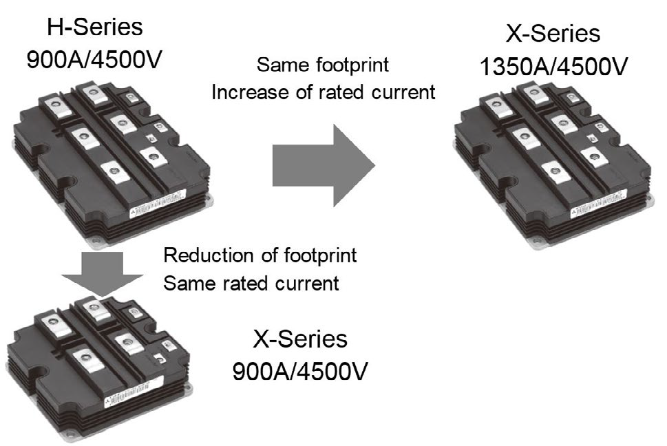
Figure 1: 4500V X-Series line-up expansion
The standard package type is still very important for different applications due to availability of second source from many IGBT device manufacturers and its proven reliability record in the field for many years. Furthermore, the upgrade or increase of the inverter output power is easily achievable by using the widely commercially available components in the market like heatsinks, gate drivers and bus bars.
The targets for 4500V X-Series device development have been defined based on feedback from customers. These were the following:
- Increasing current rating and module power density
- Reduction of module power losses
- Suitable for various applications having different switching frequency ranges
Six modules have been developed [1] to fulfill the above mentioned market requirements. The overview of the developed 4500V X-Series modules is shown in table 1.
| Isolation voltage | Foot print | Type name |
|---|---|---|
| VISO 10.2 kV | 190mm x 140mm | CM1350HG-90X (VCCmax=3400V) CM1500HG-90X (VCCmax=3200V) |
| 130mm x 140mm | CM900HG-90X (VCCmax=3400V) CM1000HG-90X (VCCmax=3200V) |
|
| VISO 6 kV | 190mm x 140mm | CM1350HC-90X (VCCmax=3400V) CM1500HC-90XA (VCCmax=3000V) |
Table 1: 4500V X-Series Line-up
Improving the Module Power Density
The most challenging requirement was increasing the module power density. The development target was achieved mainly by using the new 7th Gen. Chipset. The 7th Gen. IGBT chip, shown in Figure 2, contributes several significant cutting-edge features. The Carrier Stored Trench-gate Bipolar Transistor structure (CSTBT™) allows reduction of the IGBT forward voltage. The new LNFLR (Linearly- Narrowed Field Limiting Ring) chip termination structure allows for an increase in the active chip area and thereby a reduction of the thermal resistance. Finally, the partial P-Collector technology allows a special capability to manage a wide RBSOA.
Furthermore, the overall packaging technology of 4500V X-Series is improved for managing the increased power density. The optimized internal chip layout reduces the module thermal resistance and increases the power cycling capability. As a result, the junction-tocase thermal resistance was reduced by more than 20% compared to previous R-Series (CM1350HG-90X and CM1200HG-90R). The module performance has been proven and specified for a wide operation temperature range from -50°C to 150°C. The previous 4500V module generations were specified up to 125°C.
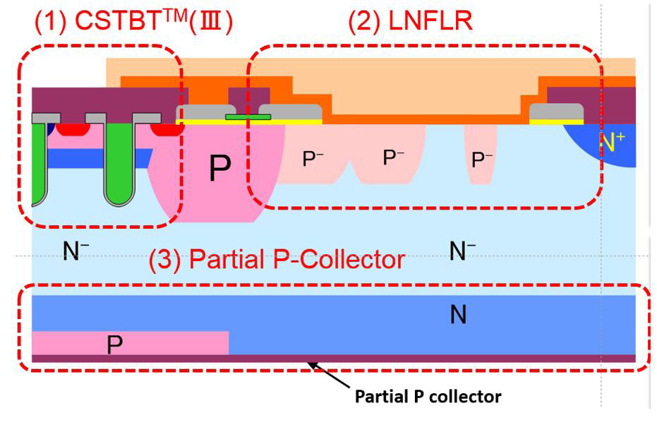
Figure 2: 4500V 7th Gen. Chip structure
Two different 7th Gen chip set are available, optimized for high and low switching frequency applications respectively. The X-Type chip set is designed for high switching frequency application (> 350Hz). The XA-type chip set achieves the lowest possible forward voltage for the IGBT and the diode. The intended switching frequency ranges from 100Hz to 350Hz. The trade-off between the forward voltage and reverse recovery switching energy for X- and XA- diode is shown in Figure 3.
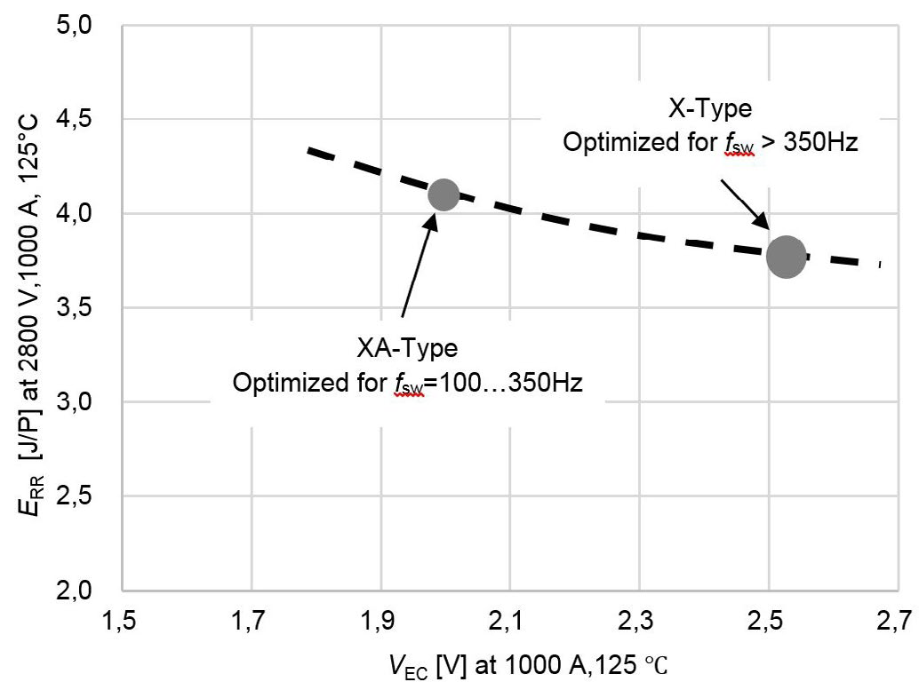
Figure 3: Diode trade-off between X- and XA device type
Safe Operating Area (SOA) for Each Application
The DC-link voltage is one of the most important stress factors influencing the SOA of IGBT module. Some applications do not require high DC-link voltage. For such cases, the SOA and with it the permitted maximum current rating increase.
The 4500V X-Series device is designed to operate at a maximum DC-link voltage of 3400V. In this case, the module’s rated current is 1350A (CM1350HG-90X). If the required maximum DC-link voltage is reduced to 3200V, the rated current increase up to 1500A (CM1500HG-90X). Both modules have the same electrical characteristics but have different SOA specifications. Each device undergoes shipping tests according to the defined maximum DC-link voltage respectively.
Example of a 3-level NPC Inverter Application
One of the targeted applications for the 4500V modules is the medium voltage (MV) drive application. For these drives, the output voltage range is between 2.3kV and 13.2kV [2]. The most common voltage levels are: 3.3 kV, 4.16kV, 6kV and 6.6kV. For these output voltages, 3-level topology is widely used. For example, these voltages can be covered by devices such as the CM1500(1350)HG-90X (as shown in Table 2). For output voltage levels higher or equal than 4160V - series connection of 4500V modules becomes necessary.
| Inverter output voltage VOUT [Vrms] | Total required inverter DCLink voltage VDC_link [V] | IGBT blocking voltage VCES IGBT [V] | IGBT Series connection | IGBT DC-Link voltage VCC_IGBT [V] |
|---|---|---|---|---|
| 3300 | 4800 | 4500 (CM1500HG-90X) | No | 2400 |
| 4160 | 6200 | 4500 (CM1500HG-90X) | Yes | 1600 |
| 6000 | 8800 | 4500 (CM1500HG-90X) | Yes | 2200 |
| 6600 | 9600 | 4500 (CM1500HG-90X) | Yes | 2400 |
Table 2: Example for 4500V IGBT module based 3-level NPC configurations
Scalability towards lower power ranges can be realized with the CM900HG-90X device or the H- and R-Series modules. The following example shows the potential of the new X-Series compared to the first H-Series in terms of power loss reduction. For the VOUT=3300V output voltage, the necessary DC-Link voltage is about 4800V. In 3-level NPC-configurations, the IGBT module would experience the half the total DC-Link (2400V). In case the heatsink potential would be connected to the middle of the DC-Link the IGBT Module isolation voltage of 10.2 kV(rms) would be sufficient to cover in Table 2 mentioned inverter output voltages.
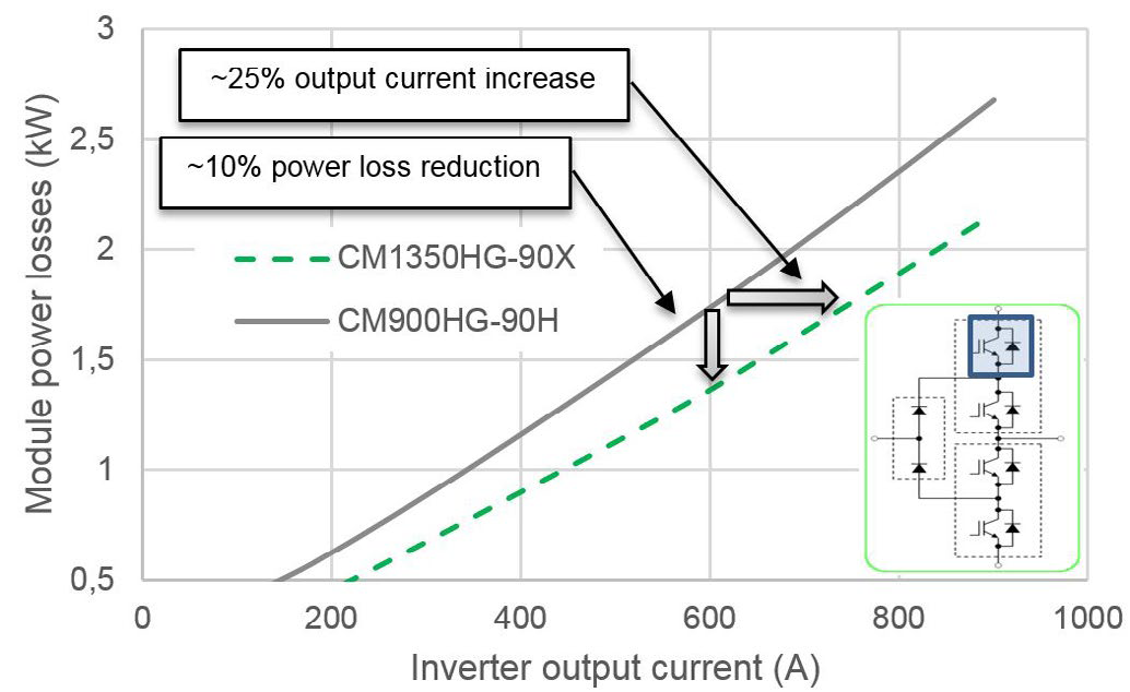
Figure 4: Comparison of the power loss simulation result using the H- and X-Series 190mm x 140mm modules.
Figure 4 shows the power loss simulation versus output current for CM900HG-90H H-Series device and CM1350HG-90X X-Series device. The simulation conditions are:
- Switching frequency fsw=0.5kHz
- Power factor p.f.=0.85
- Modulation index m=1
- Junction temperature TJ=125°C
There are two possibilities for utilizing the performance of new X-Series power modules. One possibility is a reduction of the IGBT module power losses. The power losses decrease by about 10% compared to the H-Series. The other possibility is increasing the inverter output current. The output current can be increased by about 25% compared to the H-Series. In addition, 150°C operation of X-series enables to increase even more output current than 125°C operation.
Conclusion
The newly developed 4500V X-Series enables significant increase in the inverter output power. Key enabling factors are an increased maximum junction temperature of 150°C, an improved thermal management and reduced power losses in the module. A large line-up and backward compatibility to H-Series and R-Series ensures a flexible converter design and an easy design-in. Furthermore, two different chip sets (X-type and XA-type) facilitates the optimal operation at required switching frequencies.
References
[1] Mitsubishi Electric Corporation, “Mitsubishi Electric to Expand Lineup of X-Series HVIGBT Modules,” Press Release No. 3094, May 2017
[2] Prof. Dr. M. Hiller, “Leistungselektronik mit Si-Bauelementen für die Mittelspannung”, Tagungsband des 1. Industriearbeitskreis Mittelspannungs-Leistungelektronik [Proceedings of the 1. Industry Working Group Medium-Voltage Power Electronics], Fraunhofer ISE, Berlin, Germany, 2016.
Publicaciones relacionadas
Now available – DC/DC converters from PREMIUM
We introduced a novelty to our permanent offer in DACPOL in the category of power supplies and converters and today...
Read more
New release in DACPOL lighting for lathes – Kira covers
We introduce a new product into the DACPOL category of industrial lighting and today we offer KIRA covers for...
Read more
Deja un comentario