
Debes estar logueado
Category


Las fotos son solo para fines informativos. Ver especificaciones de producto
please use latin characters
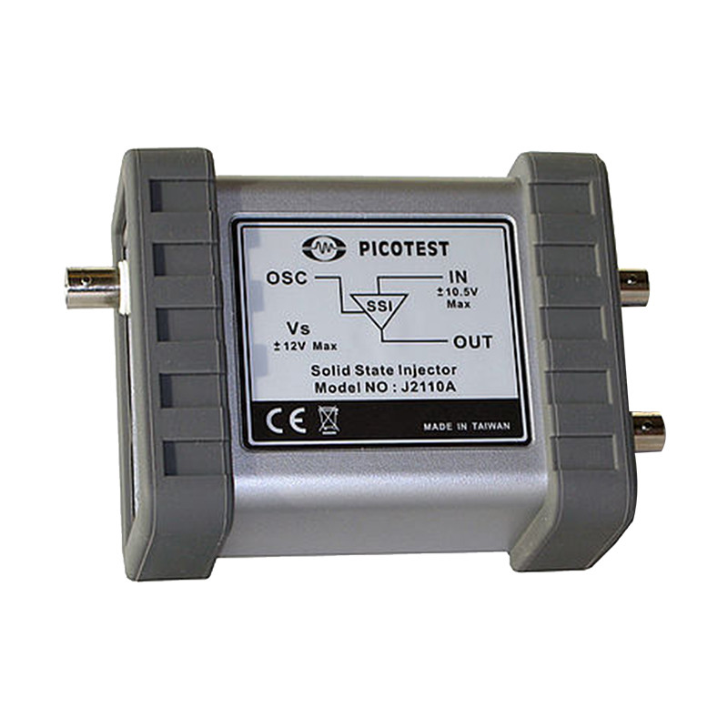
While it is possible to obtain high quality injection transformers with bandwidths as wide as 1Hz to 5MHz or more, in some cases this is still insufficient for some tests. For example a typical heater control loop might have a bandwidth of less than 1Hz while some linear regulators and opamp circuits can have bandwidths of up to 100MHz or in some cases even higher. For these applications, a solid state injector can provide the necessary bandwidth. A solid state injector can perform at DC, while the upper frequency limit is dictated by the components selected and the printed circuit board material and layout. It is possible to obtain a solid state injector with a working range of DC – 200MHz, though above 50MHz the interconnection between the injector and the circuit being tested can become quite critical. It is essential that ripple from the injector power supply does not dramatically degrade the dynamic range or the signal to noise ratio of the measurement. The resulting plots are often much cleaner when using a solid state injector than with a transformer injector.
Key features:
The selection of a valid injection point in the circuit is more critical when using a solid state injector than with the transformer injector. The solid state injector presents an infinite impedance between the points of injection. In order to provide correct results one side of the measurement must present a much higher impedance than the other side. In a typical power supply control loop, the voltage sense divider is generally a good injection point, since the output impedance of the power supply is very low compared with the impedance of the voltage sense divider.
The solid state injector has a limitation in the operating voltage, with the majority limited to 10V or 12V. This is not the amplitude of the injection signal, but the peak value (positive or negative) of the signal operating voltage.
Rated data:
| Max Vcc | ±12V |
|---|---|
| Max Icc | 20mA |
| Max input voltage DC+AC | ±10.5V |
| Output voltage | ±10.5V |
| Offset voltage | 3mV |
| Bias Current | 8μA |
| -3dB Bandwidth (-10dBm) | DC…40MHz |
| Temperature range | 0…50°C |
| Maximum Altitude | 1860m |
| Dimensions | 109x90x51mm |
| Weight | 0.210kg |
| Input | BNC, MOD – BNC |
| Output | Banana |
J2110A Solid State Injector and J2100A Injection Transformer bandwidth – comparison:

Connection diagram:

¿Estás interesado en este producto? ¿Necesita información adicional o precios individuales?
Usted debe estar conectado
While it is possible to obtain high quality injection transformers with bandwidths as wide as 1Hz to 5MHz or more, in some cases this is still insufficient for some tests. For example a typical heater control loop might have a bandwidth of less than 1Hz while some linear regulators and opamp circuits can have bandwidths of up to 100MHz or in some cases even higher. For these applications, a solid state injector can provide the necessary bandwidth. A solid state injector can perform at DC, while the upper frequency limit is dictated by the components selected and the printed circuit board material and layout. It is possible to obtain a solid state injector with a working range of DC – 200MHz, though above 50MHz the interconnection between the injector and the circuit being tested can become quite critical. It is essential that ripple from the injector power supply does not dramatically degrade the dynamic range or the signal to noise ratio of the measurement. The resulting plots are often much cleaner when using a solid state injector than with a transformer injector.
Key features:
The selection of a valid injection point in the circuit is more critical when using a solid state injector than with the transformer injector. The solid state injector presents an infinite impedance between the points of injection. In order to provide correct results one side of the measurement must present a much higher impedance than the other side. In a typical power supply control loop, the voltage sense divider is generally a good injection point, since the output impedance of the power supply is very low compared with the impedance of the voltage sense divider.
The solid state injector has a limitation in the operating voltage, with the majority limited to 10V or 12V. This is not the amplitude of the injection signal, but the peak value (positive or negative) of the signal operating voltage.
Rated data:
| Max Vcc | ±12V |
|---|---|
| Max Icc | 20mA |
| Max input voltage DC+AC | ±10.5V |
| Output voltage | ±10.5V |
| Offset voltage | 3mV |
| Bias Current | 8μA |
| -3dB Bandwidth (-10dBm) | DC…40MHz |
| Temperature range | 0…50°C |
| Maximum Altitude | 1860m |
| Dimensions | 109x90x51mm |
| Weight | 0.210kg |
| Input | BNC, MOD – BNC |
| Output | Banana |
J2110A Solid State Injector and J2100A Injection Transformer bandwidth – comparison:

Connection diagram:

Su agradecimiento a la reseña no pudo ser enviado
Reportar comentario
Reporte enviado
Su reporte no pudo ser enviado
Escriba su propia reseña
Reseña enviada
Su reseña no pudo ser enviada
