shopping_cart
Chariot
0,00 PLN
0
Cache
Vous devez être connecté
-
-
-
Category
-
Semi-conducteurs
- La diode
- Les thyristors
- Modules de puissance isolés
- Ponts redresseurs
-
Transistors
- Transistors | GeneSiC
- Modules MOSFET SiC | Mitsubishi
- Modules MOSFET SiC | STARPOWER
- Modules MOSFET SiC ABB
- Modules IGBT | MITSUBISHI
- Modules de transistors | MITSUBISHI
- Modules MOSFET | MITSUBISHI
- Modules de transistors | ABB
- Modules IGBT | POWEREX
- Modules IGBT | INFINEON (EUPEC)
- Composants semiconducteurs en carbure de silicium
- Przejdź do podkategorii
- Circuits de commande
- Blocs de puissance
- Przejdź do podkategorii
- Transducteurs électriques
-
Composants passifs (condensateurs, résistances, fusibles, filtres)
- Résistances
-
Fusibles
- Fusibles miniatures pour c.imp. série ABC et AGC
- Fusible rapides tubulaires
- Cartouches de courbe GL/GG et AM
- Cartouches ultrarapides
- Fusibles à action rapide (norme britannique et américaine)
- Fusibles à action rapide (norme européenne)
- Fusibles de traction
- Cartouche de haute tension
- Przejdź do podkategorii
-
Condensateurs
- Condensateurs pour moteurs
- Condensateurs électrolitiques
- Condensateurs de type snubbers
- Condensateurs de puissance
- Condensateurs pour circuits continus
- Condensateurs de compensation de puissance
- Condensateurs de haute tension
- Condensateurs pour chauffage par induction
- Condensateurs pour impulsions
- Condensateurs DC LINK
- Condensateurs pour circuits AC/DC
- Przejdź do podkategorii
- Filtres anti-interférences
- Supercondensateurs
- Protection contre les surtensions
- Filtres de détection des émissions TEMPEST
- Parafoudre
- Przejdź do podkategorii
-
Relais et contacteurs
- Théorie relais et contacteurs
- Relais statiques triphasés
- Relais statiques CC
- Régulateurs, circuits de commande et accessoires
- Démarrages progressifs et contacteurs inverseurs
- Relais electromécaniques
- Contacteurs
- Commutateurs rotatifs
-
Relais statiques monophasés
- Relais semi-conducteurs AC monophasés, série 1 | D2425 | D2450
- Relais à semi-conducteurs CA monophasés, séries CWA et CWD
- Relais à semi-conducteurs CA monophasés des séries CMRA et CMRD
- Relais à semi-conducteurs CA monophasés, série PS
- Relais semi-conducteurs AC double et quadruple, série D24 D, TD24 Q, H12D48 D
- Relais statiques monophasés, série GN
- Relais à semi-conducteurs CA monophasés, série CKR
- Relais AC monophasés SÉRIES ERDA ET ERAA pour rail DIN
- Relais CA monophasés pour courant 150A
- Relais à semi-conducteurs doubles intégrés à un dissipateur thermique pour un rail DIN
- Przejdź do podkategorii
- Relais statiques monophasé pour c.imp.
- Relais d'interface
- Przejdź do podkategorii
- Composants inductifs
- Radiateurs, varistances, protections thermiques
- Ventilateurs
- Climatiseurs et accessoires d'armoires électriques
-
Batteries, chargeurs, blocs d'alimentation tampon et onduleurs
- Batteries et Chargeurs - théorie
- Batteries Li-ion et non-standards. Systèmes de gestion des batteries (BMS)
- Batteries
- Chargeurs de batteries et accessoires
- Alimentation de secours UPS et alimentation tampon
- Convertisseurs de tension et accessoires pour photovoltaïque
- Stockage d'Energie
- Réservoirs de carburant
- Batteries lithium-ion
- Przejdź do podkategorii
-
Automatique industrielle
- Élévateurs Spiralift
- Pièces pour drones Futaba
- Interrupteurs de fin de course, micro-rupteurs
- Capteurs et convertisseurs
- Pyromètres
- Compteurs, Relais temporisés, Indicateurs de tableau
- Appareils industriels de protection
- Signalisation lumineuse et sonore
- Caméra thermique
- Afficheurs à LED
- Boutons et commutateurs
- Przejdź do podkategorii
-
Câbles et chemins de câbles
- Fils
- Passe-câbles et coupleurs
- Fils de Litz
- Câbles pour les applications spéciales
- Gaines
-
Tresses
- Tresses plates
- Tresses rondes
- Tresses très souples - plates
- Tresses très souples - rondes
- Tresses cuivre cylindriques
- Tresses cuivre cylindriques et protection
- Bandes de mise à la terre souples
- Tresses en acier zingué et inox
- Tresses isolantes en PVC - temp. 85°C
- Tresses plates en aluminium
- Kit de liaison - tresses et gaines
- Przejdź do podkategorii
- Equipement pour la traction
- Cosses
- Barres flexible isolées
- Barre flexibles multicouches
- Systèmes de traçage des câbles
- Przejdź do podkategorii
- Contactez-nous !
-
Semi-conducteurs
-
-


Power Modules for Combining Innovation, Flexibility and Power Capability in the Various 3-Level Topologies

Power Modules for Combining Innovation, Flexibility and Power Capability in the Various 3-Level Topologies
Three level topologies have demonstrated higher efficiencies, filter optimization potential and the capability of handling high DC-link voltages. To maximize the advantages offered by the 3-level topologies, Mitsubishi Electric offers new power modules which unlock the potential to realize innovative solutions for different power segments.
By Narender Lakshmanan and Thomas Radke, Mitsubishi Electric Europe B.V. and Satoshi Kawabata, Mitsubishi Electric Corporation Japan Power Device Works
Power conversion applications have always had to deliver high performance while maintaining the required quality of power. The harmonic profile of the output power can be improved by increasing the switching frequency. However, an increase in switching frequency compromises the inverter efficiency. Historically, the conventional 2-level inverters have served the industry with its seemingly uncomplicated topology where developers have always had to strike a balance between efficiency and filter optimization. With the invention of the 3-level topologies, many new avenues are now open for improving the output harmonic profile without compromising on the system efficiency. With the option of being able to apply the ‘zero’ level, this topology brings with it the following inherent benefits:
- Efficiency and output power capability [1]: The superior switching loss profile of a 3-level inverter ensures that better efficiencies can be achieved. Thus, for the same dc-link, a 3-level based inverter can deliver a higher output power compared to the corresponding 2-level inverter.
- AC filtering [5]: For the same switching frequency, the 3-level topology utilizes the availability of the ‘zero’ level to deliver an AC output of higher power quality than the corresponding 2-level inverter. This naturally allows a significant reduction of the output filter inductance.
- dv/dt Filter [5]: Since the phase to neutral output of a 3-level inverter shifts between 0V and (+/- Vdc)/2 (unlike the 2-level output), the corresponding dv/dt across the load is naturally reduced by about 50%.
- Common mode voltage reduction [5][6]: In comparison with 2-level, significant reduction (about 25%) of common mode voltage is possible in the 3-level topology.
While every segment of the inverter industry can avail the benefits associated with the 3-level topologies, grid connected inverters (Solar, Wind, HVDC), UPS and medium-tohigh power drives stand to benefit significantly by employing this innovative approach [3][4].
Power Modules from Mitsubishi Electric for 3-level NPC inverters
The CM400ST-24S1 module has already been introduced and presented in good detail ([2] Bodos article Feb’2015). A new series of power modules with innovative packaging optimized for 3-level applications has been developed. The comprehensive line-up is shown in Figure 1. The CM500C2Y-24S is provided as a dedicated neutral clamp switch for efficiently realizing the T type 3-level topology.
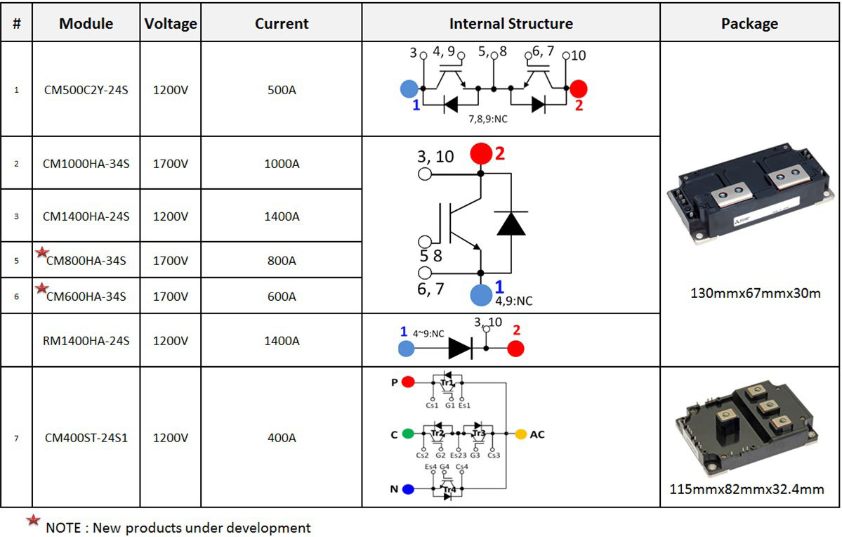
Figure 1: Line-up of the products dedicated for 3-level solutions
These power modules from Mitsubishi Electric are optimized for 3-level topologies with regards to the following parameters:
- Compact package size: For realizing an I type topology, in comparison with its counterparts from other manufacturers, the 1 in 1 modules (each 130 mm x 67 mm x 30 mm in size) offer about 20% reduction in mounting area. This was achieved by taking advantage of the superior thermal behavior of the Aluminium nitride (AlN) substrate and combining it with the CSTBT™ chip technology.
- Reduced internal inductance: The 1 in 1 modules have an internal inductance of only 8 nH. Internal stray inductance plays an important role in 3-level topologies as several elements are connected in series unlike the traditional 2-level topologies.
- Reduced overall inductance: The combination of a low internal inductance, a reduced mounting area and the location of terminals for easy connections ensure a reduced overall inductance for the set-up.
- Access to auxiliary terminals: The module provides access to the auxiliary terminals on two sides for the connecting the gate driver (without having the need to disturb the bus bar arrangement).
An example of how low inductance I-type and T-type 3-level topology bus bar designs can be realized is represented in Figure 2. As shown in this example, it is obvious that these modules are specifically optimized for 3-level topologies, thereby addressing the challenges associated with DC bus bar inductance, power density and flexibility.
Figure 3 shows the different power levels achievable by developing various 3-level topologies employing power modules from Mitsubishi Electric. The power levels are based on a conservative dimensioning of junction-case temperature rise of 25K considering a switching frequency of 2 kHz. Depending on the cooling system and the switching frequency, the output can obviously be further maximized.
Power levels
- 125 kW to 500 kW range: For a DC link voltage of 850 V, the CM400ST-24S1 with its inbuilt T type topology can deliver up to 250 kW in stand-alone mode. When used in parallel, about 500 kW output can be delivered.
- 500 kW to 2 MW range: When a DC link voltage of 1200V is utilized, two CM1000HA-34S (1000A/1700V) together with two CM500C2Y-24S (500A /1200V) in parallel can be employed to achieve more than 1 MW output. On the other hand, when an 850V DC link is considered, two CM1400HA-24S (1400A/1200V) can be employed together with two CM500C2Y in parallel to achieve more than 1 MW output power. With a DC link of 2400V, six CM1000HA-34S can be employed to develop a 1.8 MW inverter. Remarkably, utilizing a 1700V DC link, more than 2 MW output can be achieved by employing four CM1400HA-24S modules along with two RM1400HA-24S (neutral clamp diodes).
- Extended Megawatt range: It is obvious that by paralleling the options provided above, extended megawatt range inverters can be realized. An alternative solution for this class is to employ multi-level topologies.
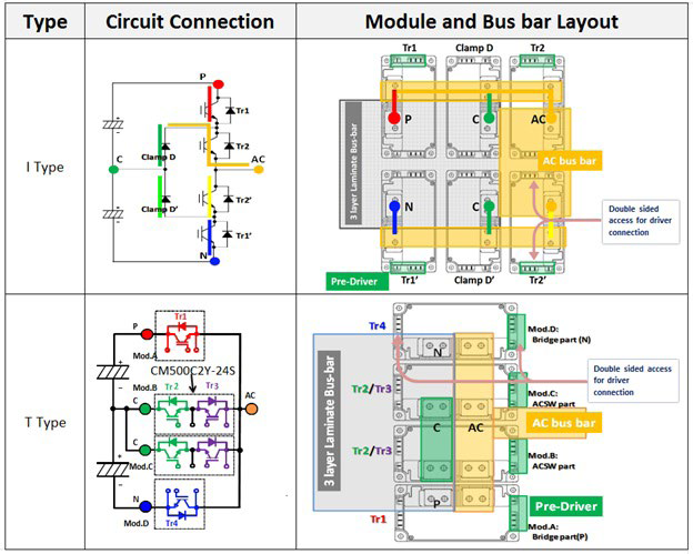
Figure 2: Sample 3-level constructions which can be realized for using Mitsubishi Electric power modules
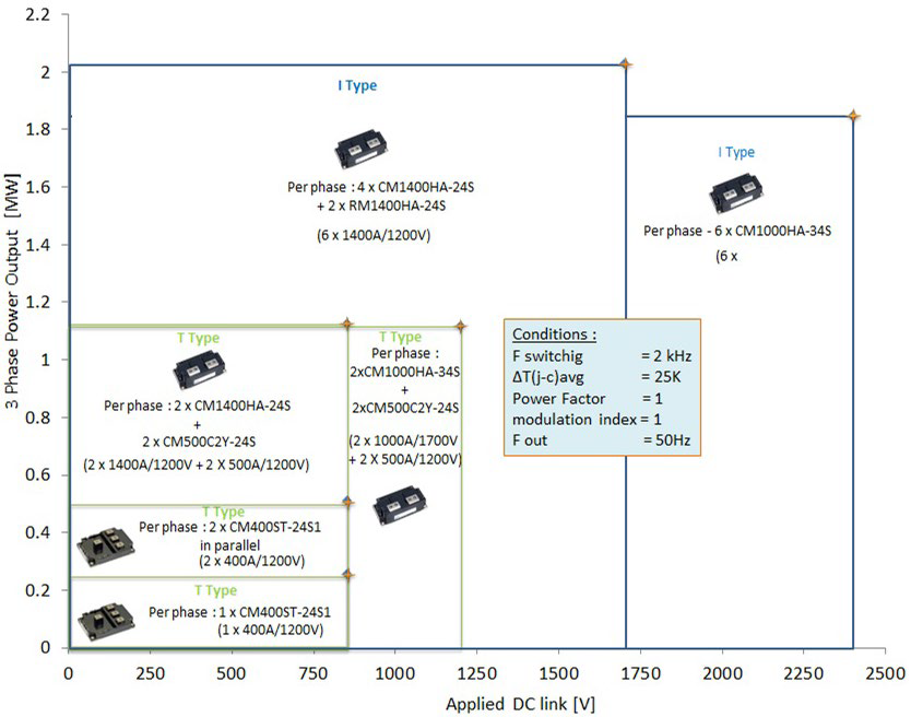
Figure 3: Power capability matrix for different 3-level solutions
As a result of these new products being available, the designer can choose the best fitting solution considering the power and DC voltage requirements. The designer is thus able to evaluate and accordingly select a suitable system voltage to achieve significant system level benefits and thereby maximize overall efficiency.
Employing the appropriate solution
Figure 4 shows that for an inverter with 1200V dc-link voltage, the maximum output current achievable for different switching frequencies for a maximum allowable ΔT(j-c) avg = 25K (imposed on the first element in any module to reach this limit) depends on the topology employed. The T type topology has advantages with respect to a lower part count and the corresponding volume reduction. However, the equivalent I type topology brings forth interesting system level benefits. Considering a fixed switching frequency of 3 kHz, it can be seen that the I type inverter is capable of delivering 1.41 times more current than the equivalent T type topology. Such benefit in power capability can also be used to allow an increase in the switching frequency (a factor of 2.66 for the 800A range) bringing significant benefits in passive component reduction. Depending on the weightage allocated to passives dimensioning and device count, an appropriate decision can be made.
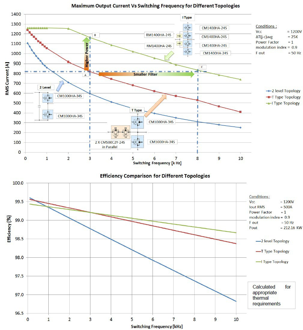
Figure 4: Analysis and comparison of performance using 3-level and 2-level topologies
Conclusion
While each module is designed to deliver the best electrical performance, the module packaging itself and the layout as well is optimized for 3-level inverter design. Combining these aspects with the variety of combinations possible using these different modules, designers now are allowed greater flexibility in realizing solutions which cater to their specific needs. To sum things up - it is clear, that there is flexibility in mechanical layout and flexibility in system level design parameters (choice of DC-link, filter). By addressing the specific needs of individual applications, it is obvious that solutions based on Mitsubishi Electric 3-level modules help achieve the maximum possible overall efficiency along with the best possible performance.
References
[1] MELCOSIM: IGBT thermal and loss simulation software, available at www. mitsubishielectric.com/semiconductors/ simulator/
[2] Marco Honsberg and Thomas Radke : “4in1 400A/1200V Module with T-type Topology for 3-Level Applications” Bodos Power Feb’2015, pages 26-28.
[3] Marco Honsberg, Thomas Radke : “3-level IGBT modules with Trench Gate IGBT and their thermal analysis in UPS, PFC and PV operation modes” - EPE 2009 – Barcelona - ISBN: 9789075815009
[4] Marco Honsberg and Thomas Radke : “A family of 3-level IGBT modules from 10A to 600A equipped with Trench Gate IGBT and their thermal performance under typical conditions for UPS and PV inverter operation” PCIM 2009 ISBN: 978-3-8007-3158-9
[5] L. Caballero, S. Ratés, O. Caubet, S. Busquets-Monge: Advantages of ac-ac power converters based on ANPC topology for wind applications”
[6] International Journal of Conceptions on Electrical & Electronics Engineering Vol. 1, Issue. 2, December 2013; ISSN: 2345 – 9603 : “Reduction of common mode voltage in three level neutral point diode clamped multilevel inverter using space vector pulse width modulation”
[7] Application note : 3-level application using 1 in 1, 2 in 1 and the 4 in 1 modules.
Articles similaires
Now available – DC/DC converters from PREMIUM
We introduced a novelty to our permanent offer in DACPOL in the category of power supplies and converters and today...
Read more
New release in DACPOL lighting for lathes – Kira covers
We introduce a new product into the DACPOL category of industrial lighting and today we offer KIRA covers for...
Read more
Laissez un commentaire