shopping_cart
Chariot
0,00 PLN
0
Cache
Vous devez être connecté
-
-
-
Category
-
Semi-conducteurs
- La diode
- Les thyristors
- Modules de puissance isolés
- Ponts redresseurs
-
Transistors
- Transistors | GeneSiC
- Modules MOSFET SiC | Mitsubishi
- Modules MOSFET SiC | STARPOWER
- Modules MOSFET SiC ABB
- Modules IGBT | MITSUBISHI
- Modules de transistors | MITSUBISHI
- Modules MOSFET | MITSUBISHI
- Modules de transistors | ABB
- Modules IGBT | POWEREX
- Modules IGBT | INFINEON (EUPEC)
- Composants semiconducteurs en carbure de silicium
- Przejdź do podkategorii
- Circuits de commande
- Blocs de puissance
- Przejdź do podkategorii
- Transducteurs électriques
-
Composants passifs (condensateurs, résistances, fusibles, filtres)
- Résistances
-
Fusibles
- Fusibles miniatures pour c.imp. série ABC et AGC
- Fusible rapides tubulaires
- Cartouches de courbe GL/GG et AM
- Cartouches ultrarapides
- Fusibles à action rapide (norme britannique et américaine)
- Fusibles à action rapide (norme européenne)
- Fusibles de traction
- Cartouche de haute tension
- Przejdź do podkategorii
-
Condensateurs
- Condensateurs pour moteurs
- Condensateurs électrolitiques
- Condensateurs de type snubbers
- Condensateurs de puissance
- Condensateurs pour circuits continus
- Condensateurs de compensation de puissance
- Condensateurs de haute tension
- Condensateurs pour chauffage par induction
- Condensateurs pour impulsions
- Condensateurs DC LINK
- Condensateurs pour circuits AC/DC
- Przejdź do podkategorii
- Filtres anti-interférences
- Supercondensateurs
- Protection contre les surtensions
- Filtres de détection des émissions TEMPEST
- Parafoudre
- Przejdź do podkategorii
-
Relais et contacteurs
- Théorie relais et contacteurs
- Relais statiques triphasés
- Relais statiques CC
- Régulateurs, circuits de commande et accessoires
- Démarrages progressifs et contacteurs inverseurs
- Relais electromécaniques
- Contacteurs
- Commutateurs rotatifs
-
Relais statiques monophasés
- Relais semi-conducteurs AC monophasés, série 1 | D2425 | D2450
- Relais à semi-conducteurs CA monophasés, séries CWA et CWD
- Relais à semi-conducteurs CA monophasés des séries CMRA et CMRD
- Relais à semi-conducteurs CA monophasés, série PS
- Relais semi-conducteurs AC double et quadruple, série D24 D, TD24 Q, H12D48 D
- Relais statiques monophasés, série GN
- Relais à semi-conducteurs CA monophasés, série CKR
- Relais AC monophasés SÉRIES ERDA ET ERAA pour rail DIN
- Relais CA monophasés pour courant 150A
- Relais à semi-conducteurs doubles intégrés à un dissipateur thermique pour un rail DIN
- Przejdź do podkategorii
- Relais statiques monophasé pour c.imp.
- Relais d'interface
- Przejdź do podkategorii
- Composants inductifs
- Radiateurs, varistances, protections thermiques
- Ventilateurs
- Climatiseurs et accessoires d'armoires électriques
-
Batteries, chargeurs, blocs d'alimentation tampon et onduleurs
- Batteries et Chargeurs - théorie
- Batteries Li-ion et non-standards. Systèmes de gestion des batteries (BMS)
- Batteries
- Chargeurs de batteries et accessoires
- Alimentation de secours UPS et alimentation tampon
- Convertisseurs de tension et accessoires pour photovoltaïque
- Stockage d'Energie
- Réservoirs de carburant
- Batteries lithium-ion
- Przejdź do podkategorii
-
Automatique industrielle
- Élévateurs Spiralift
- Pièces pour drones Futaba
- Interrupteurs de fin de course, micro-rupteurs
- Capteurs et convertisseurs
- Pyromètres
- Compteurs, Relais temporisés, Indicateurs de tableau
- Appareils industriels de protection
- Signalisation lumineuse et sonore
- Caméra thermique
- Afficheurs à LED
- Boutons et commutateurs
- Przejdź do podkategorii
-
Câbles et chemins de câbles
- Fils
- Passe-câbles et coupleurs
- Fils de Litz
- Câbles pour les applications spéciales
- Gaines
-
Tresses
- Tresses plates
- Tresses rondes
- Tresses très souples - plates
- Tresses très souples - rondes
- Tresses cuivre cylindriques
- Tresses cuivre cylindriques et protection
- Bandes de mise à la terre souples
- Tresses en acier zingué et inox
- Tresses isolantes en PVC - temp. 85°C
- Tresses plates en aluminium
- Kit de liaison - tresses et gaines
- Przejdź do podkategorii
- Equipement pour la traction
- Cosses
- Barres flexible isolées
- Barre flexibles multicouches
- Systèmes de traçage des câbles
- Przejdź do podkategorii
- Contactez-nous !
-
Semi-conducteurs
-
-


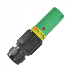
5 Best Methods for Installing POWERSAFE (POWERLOCK) Connectors
 Connectors")
5 Best Methods for Mounting POWERLOCK Connectors Step by Step
Looking for reliable and effective methods for mounting power connectors? Phase 3 Connectors has provided a detailed guide that describes step-by-step the three most popular methods: screwing, mounting on threaded sleeve, and clamping. In this article, we will focus on the first two methods, discussing their key steps and recommendations.
Screwing Method for Mounting POWERLOCK Connectors
The screwing method is one of the most commonly used methods for mounting power connectors. Here are the steps to correctly terminate a cable using this method:
Step 1: Preparation
- Unpack the packaging and remove the cable gland and contact.
- Check the cable diameter. The standard black gland M40A is designed for cables with a diameter of 19-28 mm. If the cable has a diameter between 15 and 18 mm, the reducer PP00131 should be applied to the M40A gland.
Step 2: Cable Preparation
- Slide the cable gland along the cable sheath.
- Apply the appropriate end collar or combination of collars to the conductors. Ensure that all conductor cores are inside the end collar.
Step 3: Cable Termination
- Carefully remove the cable insulation by 33 mm. Try not to damage any of the conductor cores.
Step 4: Screwing
- Insert the cable and reducers into the back of the contact, ensuring they are fully inserted inside the contact. Use a 5 mm wrench to tighten the screws according to the table.
Mounting on Threaded Sleeve Method for POWERLOCK Connectors
Another popular method for mounting power connectors is mounting on a threaded sleeve. Here's how to do it step by step:
Step 1: Inserting the Contact
- Insert the contact into the back of the insulator and align the hole in the contact to be in line with the holes in the insulator.
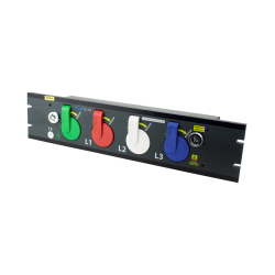
Step 2: Mounting the Threaded Sleeve
- When the panel connector is mounted in the device, remove the nut and washer from the threaded part.
- Place the selected terminal or accessory on the threaded area.
- Reapply the washer and screw onto the threaded area, tightening to a maximum of 12-14 Nm.
With these detailed instructions, mounting power connectors becomes simple and effective. Let's now move on to the next part, where we will discuss step by step the clamp methods and the termination of connector mounting.
Crimping Pins Method
The last method we'll discuss is the crimping method, which requires special tools to perform the assembly correctly. Here's how to proceed:
Step 1: Tool Preparation
- Ensure you have the appropriate crimping tools, including the correct jaw set.
Step 2: Selecting Crimping Set
- Choose the appropriate crimping set based on the cable size. For example, if you're using a cable with a cross-section of 240 mm², use the ME48 set.
Step 3: Cable Preparation
- Remove the cable insulation, leaving 43 mm of exposed wires.
Step 4: Wire Insertion
- Insert the wire into the back of the contact, ensuring all wire strands are inside the contact.
Step 5: Crimping
- Carefully place the contact and wire into the crimping tool and close the tool. When the tool achieves the proper compression, you will feel and hear a click. Then, the tool can be opened to release the crimped contact.
When selecting the appropriate mounting method, always follow the manufacturer's recommendations and strictly adhere to the steps. Let's now proceed with the termination of connector mounting and discuss safety and maintenance procedures.
Clamping Method
The clamping method involves mechanically clamping wires using special clamps, ensuring a solid electrical connection. Here are the steps for mounting a connector using this method:
Step 1: Wire Preparation
- Prepare the wire appropriately by removing insulation to a specified length and bending a small portion of the wire end at a 90-degree angle.
Step 2: Inserting Wire into Connector
- Insert the appropriate wire end into the clamping connector, ensuring all wire strands are properly positioned.
- Use a special crimping tool to securely clamp the connector onto the wire. Ensure that the crimping is sufficiently strong to provide a reliable connection.
Soldering POWERLOCK Connectors Method
The soldering method involves connecting wires by melting solder and joining it with connector elements. Here are the steps for mounting a connector using this method:
Step 1: Wire Preparation
- Remove the wire insulation to a specified length and clean the exposed wire section using a cleaning agent or sandpaper.
- Apply solder to the cleaned wire section and the appropriate connector part.
- Insert the cleaned wire into the connector and solder it using a soldering iron, ensuring a solid connection.
Completing Connector Mounting and Safety Procedures
Termination of power connectors is a key element in ensuring a reliable electrical connection. After completing the mounting of connectors, it's important to perform safety and maintenance procedures to ensure long-term performance and safety of the connection.
Safety Procedures:
- 1. Regular Insulator Checks: Periodically inspect the outer surface of insulators for cracks or damage. If any signs of damage are detected, the insulator should be replaced.
- 2. Check Cable Gasket Tightness: During use, cable gaskets may loosen, leading to water ingress. Regularly checking the tightness of gaskets is therefore essential.
- 3. O-ring Seal Inspection: If you suspect O-ring seal degradation, they should be replaced. Seals should be in good condition and properly positioned inside the connectors.
- 4. Regularly check the condition of the front sealing ring. Additionally, applying a thin layer of silicone grease to the sealing ring surface will allow for easy mating and protect the ring from degradation.
Performing these procedures after mounting power connectors is crucial to ensuring long-term performance and safety of the connection. They can help avoid potential failures and hazards to the electrical system.
If needed, service replacement parts are readily available from the manufacturer. It's also important to remember that any work related to the installation, inspection, and maintenance of power connectors should be carried out only by qualified electricians, following local and national electrical regulations.
Summary
Mounting POWERLOCK connectors requires precision and the right tools, but also strict adherence to the manufacturer's recommendations. With detailed instructions, you can effectively assemble cables, ensuring reliability and safety of the connection.
Produits associés

Articles similaires
Now available – DC/DC converters from PREMIUM
We introduced a novelty to our permanent offer in DACPOL in the category of power supplies and converters and today...
Read more
New release in DACPOL lighting for lathes – Kira covers
We introduce a new product into the DACPOL category of industrial lighting and today we offer KIRA covers for...
Read more
Laissez un commentaire