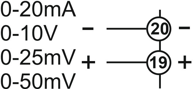
Input type selection: 0-20mA, 4-20mA, 0-10V, 2-10V, 0-25mV, and 0-50mV
Programmable digital contact input D1 and D2
Automatic PID parameter calculation (SELF TUNE)
Before the system's first operation, if the PID parameters are known, they should be entered; otherwise, the self-tuning function should be activated.
Control outputs can be disabled (used for measurements)
Manual control of outputs C/A2 or ANL/SSR
Soft start function
Communication via RS485 Modbus protocol
Selectable control outputs: analog, SSR, or relay
Selectable analog output: 0-20mA, 4-20mA
Relay output C/A2 can be set as an additional alarm or temperature control output
Heating/cooling control type selection
Input offset function
In case of sensor failure, relay position selection or periodic operation can be performed
Profile control function up to 16 steps
Optional contact output triggering function at profile steps
Timer or thermostat function can be used during profile control
Heating error monitoring function
Access to all parameters via NFC
CE marking compliant with European standards
Technical Data
Parameter
Value
Power Supply
24V DC
Maximum Power Consumption
5VA
Connection
1.5mm2 screw terminal
Maximum Terminal Connection Resistance
100Ω for thermocouple, 20Ω for three-wire PT100
Ambient/Storage Temperature
0…+50°C/-25…+70°C (non-condensing)
Protection Class
Compliant with EN 60529 IP20
Hysteresis
Adjustable range 1…50°C/F
Inputs
Parameter
Value
Power Supply
24V DC
Maximum Power Consumption
5VA
Connection
1.5mm2 screw terminal
Maximum Terminal Connection Resistance
100Ω for thermocouple, 20Ω for three-wire PT100
Ambient/Storage Temperature
0…+50°C / -25…+70°C (non-condensing)
Protection Class
Compliant with EN 60529 IP20
Hysteresis
Adjustable range 1…50°C/F
Inputs
Universal sensor inputs
See Sensor Inputs table (rows 1-3)
Potential-free contact input D1
Programmable input 1 for control button
See Sensor Inputs table (row 4)
Potential-free contact input D2
Programmable input 2 for control button
See Sensor Inputs table (row 4)
Outputs
Output C/A2
Relay: 250 V AC, 5 A (for resistive load), NO (control or Alarm2 output selection)
Output A1
Relay: 250 V AC, 5 A (for resistive load), NO control
ANL/SSR outputs
Selectable analog output 0-20mA and 4-20mA; SSR 15V 20mA Maximum load resistance is 500Ω on mA output and in SSR mode
Relay lifetime
10,000,000 operations without load; 250 V AC, 5 A (resistive load) 300,000 operations
Housing
Housing type
DIN rail-mounted housing compliant with DIN 43 700
Dimensions (width x height x depth)
22.5 x 96 x 86 mm
Weight
approx. 158 g (packed)
Housing material
Self-extinguishing plastic
Wiring Diagram
Translation:
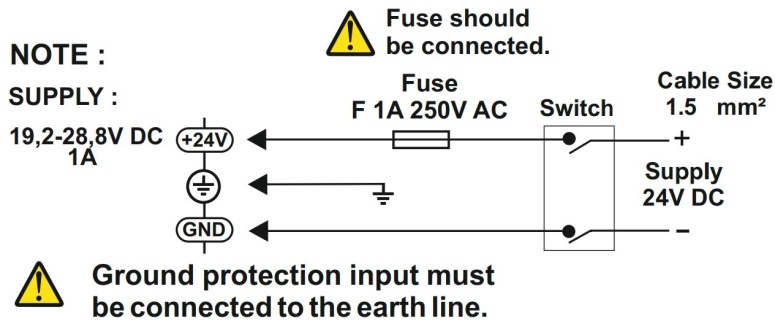
Note – Uwaga
Supply – Zasilanie
Fuse should be connected. – Bezpiecznik powinien być podłączony.
Fuse – bezpiecznik
Switch – przełącznik
Cable size – rozmiar przewodu
Ground protection input must be connected to the earth line. – Wejście uziemiające musi być podłączone do linii uziemienia.
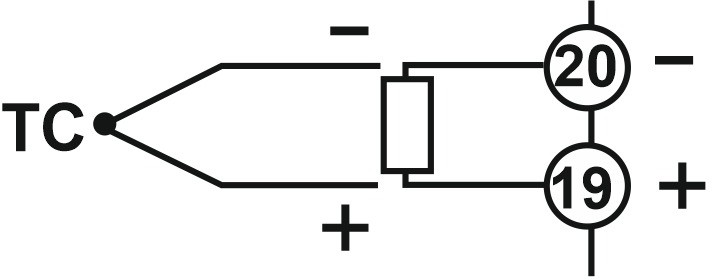
• Thermocouples type J-K-L-T-S-R: Use appropriate compensation cables for thermocouples. Do not use jointed cables. Ensure input terminals are connected correctly with proper polarity as shown in the figure.
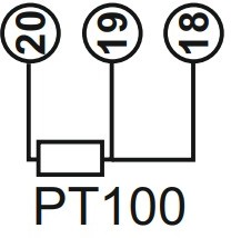
• Resistance (Pt100) thermocouples:
For two-wire PT100 sensors, short-circuit terminals 2 and 3. Do not use jointed cables. Long cables cause incorrect temperature measurement.
Ensure correct connection and proper polarity at the input terminals as shown in the figure. Do not use jointed cables. Long cables cause incorrect measurement results.
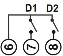
• Potential-free contact inputs D1 and D2:
Potential-free contacts must be used with mechanical keys.
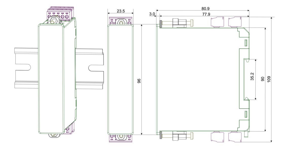
Dimensions (in mm)
Controller Programming
The controller can be programmed via the ENDALink application by bringing a phone with NFC function close. All parameters can be read and configured in the application. A detailed description of the parameters is in the catalog note. QR codes for scanning and installing the application:
Input type selection: 0-20mA, 4-20mA, 0-10V, 2-10V, 0-25mV, and 0-50mV
Programmable digital contact input D1 and D2
Automatic PID parameter calculation (SELF TUNE)
Before the system's first operation, if the PID parameters are known, they should be entered; otherwise, the self-tuning function should be activated.
Control outputs can be disabled (used for measurements)
Manual control of outputs C/A2 or ANL/SSR
Soft start function
Communication via RS485 Modbus protocol
Selectable control outputs: analog, SSR, or relay
Selectable analog output: 0-20mA, 4-20mA
Relay output C/A2 can be set as an additional alarm or temperature control output
Heating/cooling control type selection
Input offset function
In case of sensor failure, relay position selection or periodic operation can be performed
Profile control function up to 16 steps
Optional contact output triggering function at profile steps
Timer or thermostat function can be used during profile control
Heating error monitoring function
Access to all parameters via NFC
CE marking compliant with European standards
Technical Data
Parameter
Value
Power Supply
24V DC
Maximum Power Consumption
5VA
Connection
1.5mm2 screw terminal
Maximum Terminal Connection Resistance
100Ω for thermocouple, 20Ω for three-wire PT100
Ambient/Storage Temperature
0…+50°C/-25…+70°C (non-condensing)
Protection Class
Compliant with EN 60529 IP20
Hysteresis
Adjustable range 1…50°C/F
Inputs
Parameter
Value
Power Supply
24V DC
Maximum Power Consumption
5VA
Connection
1.5mm2 screw terminal
Maximum Terminal Connection Resistance
100Ω for thermocouple, 20Ω for three-wire PT100
Ambient/Storage Temperature
0…+50°C / -25…+70°C (non-condensing)
Protection Class
Compliant with EN 60529 IP20
Hysteresis
Adjustable range 1…50°C/F
Inputs
Universal sensor inputs
See Sensor Inputs table (rows 1-3)
Potential-free contact input D1
Programmable input 1 for control button
See Sensor Inputs table (row 4)
Potential-free contact input D2
Programmable input 2 for control button
See Sensor Inputs table (row 4)
Outputs
Output C/A2
Relay: 250 V AC, 5 A (for resistive load), NO (control or Alarm2 output selection)
Output A1
Relay: 250 V AC, 5 A (for resistive load), NO control
ANL/SSR outputs
Selectable analog output 0-20mA and 4-20mA; SSR 15V 20mA Maximum load resistance is 500Ω on mA output and in SSR mode
Relay lifetime
10,000,000 operations without load; 250 V AC, 5 A (resistive load) 300,000 operations
Housing
Housing type
DIN rail-mounted housing compliant with DIN 43 700
Dimensions (width x height x depth)
22.5 x 96 x 86 mm
Weight
approx. 158 g (packed)
Housing material
Self-extinguishing plastic
Wiring Diagram
Translation:
Note – Uwaga
Supply – Zasilanie
Fuse should be connected. – Bezpiecznik powinien być podłączony.
Fuse – bezpiecznik
Switch – przełącznik
Cable size – rozmiar przewodu
Ground protection input must be connected to the earth line. – Wejście uziemiające musi być podłączone do linii uziemienia.
• Thermocouples type J-K-L-T-S-R: Use appropriate compensation cables for thermocouples. Do not use jointed cables. Ensure input terminals are connected correctly with proper polarity as shown in the figure.
• Resistance (Pt100) thermocouples:
For two-wire PT100 sensors, short-circuit terminals 2 and 3. Do not use jointed cables. Long cables cause incorrect temperature measurement.
Ensure correct connection and proper polarity at the input terminals as shown in the figure. Do not use jointed cables. Long cables cause incorrect measurement results.
• Potential-free contact inputs D1 and D2:
Potential-free contacts must be used with mechanical keys.
Dimensions (in mm)
Controller Programming
The controller can be programmed via the ENDALink application by bringing a phone with NFC function close. All parameters can be read and configured in the application. A detailed description of the parameters is in the catalog note. QR codes for scanning and installing the application: