Remote Monitoring Device
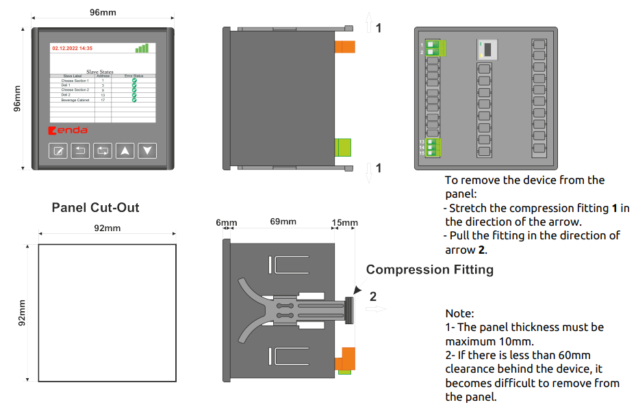
- Dimensions 96x96mm
- TFT Screen 3.5”
- On-Off Control
- Variable IP address, subnet mask, gateway, and DNS
- RS485 connection with adjustable transmission speed
- Up to 10 subordinate devices can be connected via RS485
- Ability to request parameters for connected subordinate devices
- CE marking according to EN standards

Technical Data:
| Parameter |
Size |
| Electrical Parameters |
| Supply Voltage |
90-250V AC 50/60Hz |
| Maximum Power Consumption |
7VA |
| Connections |
Power terminal 2.5mm2, signal terminal 1.5mm2 |
| Environmental Conditions |
| Operating/Storage Temperature |
0…+50°C/-25…70°C |
| Degree of Protection |
According to EN 60529; Front panel: IP65, Rear panel: IP20 |
| Enclosure |
| Mounting Type |
Mounting by compression on the panel |
| Dimensions (width x height x depth) |
96x96x81mm |
| Weight |
Approx. 400g |
| Enclosure Materials |
Uses self-extinguishing plastics |
Connection and Terminal Diagram

Note:
1) Power cables must meet the requirements of IEC 60277 or IEC 60245 standards.
2) According to safety regulations, the main switch must be in a location easily accessible to the operator and must have labeling indicating its importance to the device.
Dimensions and Installation
| Translation |
| Original |
Polish Translation |
To remove the device from the panel:
- Stretch the compression fitting 1 in the direction of the arrow.
- Pull the fitting in the direction of arrow 2. |
Aby odłączyć urządzenie od panelu:
- Rozciągnąć złączkę zaciskową 1 w kierunku wskazanym strzałką.
- Pociągnij złączkę w kierunku wskazanym strzałką 2. |
| Panel Cut-Out |
Wycięcie w panelu |
| Compression Fitting |
Mocowanie kompresyjne |
Note:
1- The panel thickness must be maximum 10mm.
2- If there is less than 60mm clearance behind the device, it becomes difficult to remove from the panel. |
Uwaga:
1- Grubość panelu musi wynosić maksymalnie 10 mm.
2- Jeśli za urządzeniem jest mniej niż 60 mm wolnej przestrzeni, usunięcie go z panelu będzie utrudnione. |
Front Panel

Buttons and Their Functions
| Button |
Description |
 |
Changing parameter in “Menu Mode” |
 |
Return to the previous page in “Menu Mode” and exit from the current tab |
 |
Enter “Menu Mode” and navigate between options in “Menu Mode” |
 |
Increase the value of the selected parameter in “Menu Mode” |
 |
Decrease the value of the selected parameter in “Menu Mode” |
Tabs in “Menu Mode” and Their Description
| Tab |
Description |
 |
Tab for entering IP addresses, subnet masks, gateways, etc. |
 |
Tab for setting BaudRate and other communication settings |
 |
Tab for pairing the ERC device with the server |
 |
Tab showing authorized email addresses |
 |
Tab showing monitored parameters |
 |
Tab for menu updates |
 |
Tab for resetting to factory settings |
Using Buttons in the Menu
- In the “Home Screen,” holding the button for 2 seconds switches to “Menu Mode”
- In “Menu Mode,” pressing returns to the “Home Screen”
- In “Menu Mode,” you can navigate between menus using the buttons
- To select the highlighted tab, press
Ethernet Tab
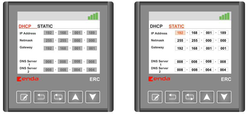
·
- To switch between DHCP and STATIC, press
- In STATIC IP mode, navigate between parameters using the buttons
- Select a parameter using the button, then change the value using
Modbus Tab

- Change the BaudRate parameter in Modbus RTU communication using the buttons, return to the menu using

| Translation |
| Original |
Polish Translation |
| MODBUS CONNECTION DIAGRAM |
Schemat połączenia Modbus |
| Master Device |
Urządzenie nadrzędne |
| Slave Device |
Urządzenie podrzędne |
| Maximum 10 slave devices can be controlled |
Maksymalnie 10 urządzeń podrzędnych może być kontrolowanych |
| The communication line should be terminated with a 120 Ohm resistor at the beginning and end. |
Linia komunikacyjna powinna posiadać terminator 120 Ohm na początku i końcu. |
Pairing Tab
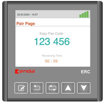
- To pair the server with the ERC device, open the pairing page (https://iot.enda.com/ -> log in using an email authorized by the manufacturer) and enter the 6-digit code displayed on the screen into the designated field on the website. Press to exit the tab.
Authorized Emails Tab

- Authorized emails can be viewed/removed in this tab
- NOTE: After removing authorized emails, the server and ERC device must be paired again to access the ERC device from the server
Monitored Slave Devices
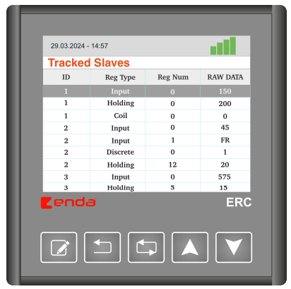
- Navigate between slave devices and parameters using the arrow buttons
- ID: ID number of the connected slave device
- Reg Type: Type of register read. Four different types of registers can be read: Input, Holding, Coil, Discrete
- Reg Num: Address of the read register.
- RAW DATA: Value of the read register. If there is a read error, the message “FR” will be displayed
Update Tab

- After entering the update page, wait for the firmware list to be updated
- Once the firmware list is updated, navigate between files using the arrow buttons . Select a file using
- After starting the file download process, wait for the download to complete and the firmware update. Do not disconnect the internet connection or power to the device during this time.
Status Bars and Error Definitions
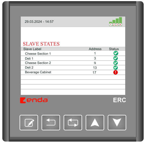
| Icon |
Definition |
Description |
 |
(1) Ethernet Status |
Indicates whether the Ethernet cable is connected to the ERC device. |
| (2) IP Status |
Indicates whether the ERC device has obtained an IP address. |
| (3) Internet Status |
Indicates whether the ERC device has an internet connection. |
| (4) Server Connection Status |
Indicates the state of the connection between the ERC device and the server. |
 |
Slave Device Error Status |
Indicates a connection error with the slave device connected to the ERC device. |
Also read:
Increase Efficiency and Safety: How the Industrial IoT Gateway ERC Modernizes Production Management
Revolution in Modern Automation: The Industrial IoT Gateway ERC from ENDA
Optimization of Plastic Production with the ENDA ERC IoT Network Gateway: Data Integration, Monitoring, and Remote Management
Industrial IoT Gateway ERC in Food Production
Industrial IoT Gateway ENDA ERC in Pharmaceutical Manufacturing


 Industrial IoT Gateway ENDA ERC – In Pharmaceutical Manufacturing
 Industrial IoT Gateway ERC in Food Production
 Enhancing Plastic Production with ENDA ERC Industrial IoT Gateway: Data Integration, Monitoring, and Remote Management