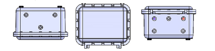
iWAP107 Universal Zone 1 Access Point Enclosure.
Admission:
ATEX II 2(1) GD
Ex d [ia IIC Ga] IIB+H2 T5 Gb
Ex tb [ia Da] IIIC T100°C Db
Overview
The iWAP107 is an ATEX and IECEx approved Zone 1 Access Point Enclosure with intrinsically safe RF outputs which is designed to allow the deployment of wireless networks in hazardous areas. The concept allows installation of equipment from leading WLAN vendors such as Cisco, Aruba, Aeroscout and Motorola. Each type of Access Point or RF transmitting device is rigorously checked and tested by Extronics to ensure conformity to the latest standards. This means that the user may select
the vendor of their choice when extending a WLAN to hazardous areas. However equipment not previously approved will require assessment to determine its suitability.
The galvanically isolated RF outputs of the iWAP107 allows users to choose non-certified antennas for use with their wireless hardware e.g. Extronics iANT2xx range of high quality rugged outdoor antennas. Any antennas not listed in the Extronics range must be assessed by the user to ensure they meet the requirements for installation of non-electrical equipment in hazardous areas. Up to eight antennas can be utilized, allowing the MIMO functionality of the latest 802.11n/ac compatible wireless
access points to be implemented, providing optimum coverage and maximum data throughput on Chemical Plants, Oil Refineries or Oil [&] Gas Platforms. Optional features include surge arrestors for lightning suppression in outdoor installations and single mode or multimode fibre optic inputs to allow for extended Ethernet link distance.
Specyfikacja
| Certification Type |
II 2 (1)GD Ex d [ia IIC Ga] IIB+H2 T5 Gb
II 2 (1)GD Ex tb [ia Da] IIIC T100°C Db |
| Power Supply |
120VAC lub 230VAC (+/- 10%) / IEEE802.3at PoE |
|
Maximum Power Consumption
|
Basic configuration: 25W
With heaters: 125W |
| Enclosure Material |
Marine grade copper free aluminium light alloy, epoxy powder coated or 316L Stainless Steel (optional) |
| Stopień ochrony |
IP66 |
| Weight |
Aluminium—Approx 30kg (hardware dependant)
316L Stainless Steel—Approx 70kg (hardware dependant) |
| Dimensions |
Aluminium— 415 x 315 x 250 mm (w x h x d)
316L Stainless Steel— 415 x 315 x 253 mm (w x h x d) |
| Environmental |
Ambient temperature: -20ºC to +60ºC (dependant on wireless hardware—see individual AP operating temperatures overleaf)
Relative humidity; 0 to 95%, non condensing |
| Input Connections |
- AC / DC power input screw terminals
- 10/100/1000Base-T Ethernet on RJ45 socket
- Single or Multi mode fibre input on LC connector [&] Splice Tray (all via M20x1.5-6H drilled entries) |
| Ethernet Link distance |
10/100/1000BASE-T Ethernet on CAT5e: up to 100m
100BASE-FX Multi Mode fibre : up to 2km, wavelength 1310nm
100BASE-LX10 Single mode fibre: up to 10km, wavelength 1310nm
1000BASE-LX Multi Mode fibre : up to 550m, wavelength 1310nm
1000BASE-LX10 Single mode fibre: up to 10km, wavelength 1310nm |
| Output Connection |
Up to eight galvanically isolated N-Type RF outputs |
| Internal RF Losses (typical) |
|
2,4GHz |
5,0GHz |
2,4/5GHz dual band |
| Without Surge Arrestor |
2,7dB |
3,6dB |
3,2dB/4,5dB |
| With Surge Arrestor |
2,8dB |
3,9dB |
3,3dB/4,8dB |
| Certification |
ATEX: TRAC14ATEX0022X
IECEx: TRC 14.0010X
NEC 500 - C1 D1: Pending |
Antenna Locations
In order that customers enjoy the best possible wireless performance from their iWAP107 system we recommend that, where possible, antennas are remotely mounted as high as possible and with sufficient separation. It is recognised that in some instances remote mounting of antennas is not a feasible option and for these circumstances we have optimised the antenna positions for the various configurations. When completing the order information for option [#10]overleaf, you must specify remote or direct mounted antennas. The RF connections will then be supplied as shown in the diagrams below depending on the total number of RF ports selected for your device.
Remote Mount - Up to 6 antennas plusData [&] Power outlets
| top face |
|
bottom face |
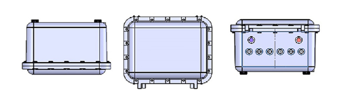 |
Direct Mount - 2 antennas plus Data [&] Power outlets
| top face |
|
bottom face |
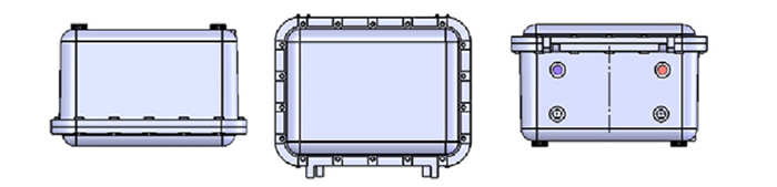 |
Direct Mount - 3 antennas plus Data [&] Power outlets
| top face |
|
bottom face |
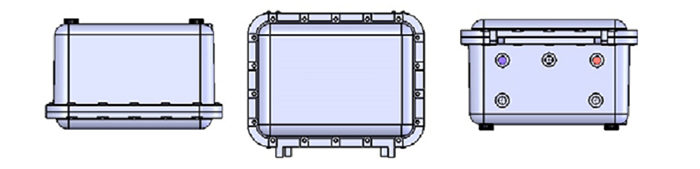 |
Direct Mount - 4 antennas plus Data [&] Power outlets
| top face |
|
bottom face |
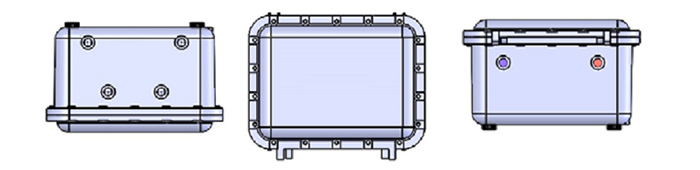 |
Direct Mount - 6 antennas (3 bottom [&] 3 top) plus Data [&] Power outlets
| top face |
|
bottom face |
 |
iWAP107 - Universal Access Point Enclosure iWAP107-[#1]-[#2]-[#3]-[#4]-[#5]-[#6]-[#7]-[#8]-[#9]-[#10]-[#11]
Specify option [#1] - Wireless Network Hardware
| Hardware supplied by customer* |
C |
| Hardware supplied by Extronics |
E |
*Extronics can supply the wireless hardware, or alternatively you may wish to “free issue” one of the already certified solutions so that we can factory fit it (see option #2 for certified hardware list). (“Free Issue” means to supply and deliver toExtronics HQ at your own cost.)
Specify option [#2] - Type Of Wireless Network Hardware (Max operating temperature listed in brackets only applies to PoE powered units, take lower value if powered by AC/DC. If the heater option is selected this will allow all AP’s to operate at a lower ambient temperature of –20 0 C.)
| Aruba AP-134 Access Point (0oC to 40/450C) |
29 |
| Configuration for AeroScout Location Receiver (00C to 45/500C) |
31 |
| Cisco AP3500 Series Access Point (-200C to 45/500C) |
33 |
| Cisco AP1260 Series Access Point (-200C to 45/500C) |
35 |
| Cisco AP1600 Series Access Point (-200C to 45/500C) |
36 |
| Cisco AP2600 Series Access Point (-200C to 45/500C) |
37 |
| Cisco AP3600 Series Access Point (-200C to 45/500C) |
38 |
| Cisco AP1530 Series Access Point (-200C to 55/600C) |
39 |
| Aruba AP-110 Series Access Point (00C to 40/450C) |
40 |
| Aruba AP-220 Series Access Point (00C to 40/450C) |
41 |
| Lancom IAP-321 (-200C to 40/450C) |
44 |
| Cisco AP3700 Series Access Point (-200C to 40/450C) |
45 |
Specify option [#3] - Power Supply
| 120V AC Supply |
AC1 |
| 230V AC Supply |
AC2 |
IEEE802.3at compliant Power-Over-Ethernet (Chosen hardware must be compatible with PoE supply)
Specify option [#4] - Ethernet Connection
| 100/1000Base-T Ethernet on CAT5e copper |
C |
| 100/1000Base-T Ethernet on CAT5e copper - surge protected |
CS |
| Multimode 100BASE-FX fibre with LC connector |
F |
| Single mode 100BASE-LX10 fibre with LC connector |
S |
| Multimode 1000BASE-LX fibre with LC connector |
FG |
| Single mode 1000BASE-LX10 fibre with LC connector |
SG |
Specify option [#5] - Frequency Output for Radio 1
| 2,4GHz |
24 |
| 5GHZ |
50 |
| Dual band output (2.4GHz [&] 5GHz) |
2450 |
Specify option [#6] - Number of Antenna Outputs for Radio 1
| 0/1/2/3/4 off N-type connector |
0/1/2/3/4 |
| 0/1/2/3/4 off N-type connector with surge protector |
0S/1S/2S/3S/4S |
Specify option [#7] - Frequency Output for Radio 2
| Not Required |
N |
| 2,4GHz |
24 |
| 5GHZ |
50 |
| Dual band output (2.4GHz [&] 5GHz) |
2450 |
Specify option [#8] - Number of Antenna Outputs for Radio 2
| 0/1/2/3/4 off N-type connector |
0/1/2/3/4 |
| 0/1/2/3/4 off N-type connector with surge protector |
0S/1S/2S/3S/4S |
Specify option [#9] - Enclosure Heating (not compatible with POE or DC supplies)
| No enclosure heating |
N |
| Supplied with enclosure heating |
H |
Specify option [#10] - Antenna Position (see previous page for antenna layout pattern which relates to total No. of RF outputs)
| Remote Mount |
R |
| Direct Mount |
D |
Specify enclosure material [#11]
| Marine grade copper free aluminium light alloy |
AL |
| Direct Mount |
SS |
Accessories
Stainless Steel 316L Enclosure Pipe mount bracket kit for iWAP107 Enclosure iWAPMB02 to fit 1.5” - 2” diameter pipe or rectangular pos


