shopping_cart
Колица
0,00 PLN
0
цлипбоард
Морате бити пријављени да
-
-
-
Category
-
Полупроводници
- диоде
- Тиристори
-
Електро изоловани модули
- Електро изоловани модули | ВИСХАИ (ИР)
- Електро изоловани модули | ИНФИНЕОН (ЕУПЕЦ)
- Електро изоловани модули | Семикрон
- Електро изоловани модули | ПОВЕРЕКС
- Електро изоловани модули | ИКСИС
- Електро изоловани модули | ПОСЕИЦО
- Електро изоловани модули | АББ
- Електро изоловани модули | ТЕЦХСЕМ
- Go to the subcategory
- Мостовни исправљачи
-
Транзистори
- Транзистори | GeneSiC
- SiC MOSFET модули | Mitsubishi
- SiC MOSFET модули | STARPOWER
- АББ СиЦ МОСФЕТ модули
- IGBT модули | MITSUBISHI
- Транзисторски модули | MITSUBISHI
- MOSFET модули | MITSUBISHI
- Транзисторски модули | ABB
- ИГБТ модули | POWEREX
- ИГБТ модули | ИНФИНЕОН (ЕУПЕЦ)
- Silicijum-karbidni poluprovodnički elementi
- Go to the subcategory
- Гате Дриверс
- Блокови напајања
- Go to the subcategory
- Električni pretvarači
-
Пасивне компоненте (кондензатори, отпорници, осигурачи, филтери)
- Otpornici
-
Osigurači
- Minijaturni osigurači za elektronske sisteme serije ABC i AGC
- Cilindrični brzi osigurači
- Osigurači sa odloženim delovanjem GL/GG i AM karakteristika
- Ultra-brzi osigurači
- Brzi osigurači sa britanskim i američkim standardom
- Brzi osigurači sa evropskim standardom
- Vučni osigurači
- Visokonaponski osigurači
- Go to the subcategory
-
Kondenzatori
- Motorni kondenzatori
- Elektrolitski kondenzatori
- Kondenzatori - snubberi
- Energetski kondenzatori
- Kondenzatori za DC kola
- kondenzatori za kompenzaciju snage
- Visokonaponski kondenzatori
- Kondenzatori za indukciono grejanje
- Impulsni kondenzatori
- ДЦ ЛИНК кондензатори
- Кондензатори за АЦ/ДЦ кола
- Go to the subcategory
- EMI filtri
- Superkondenzatori
- Заштита од пренапона
- TEMPEST филтери за откривање емисије
- Одводник пренапона
- Go to the subcategory
-
Releji i kontaktori
- Теорија релеја и склопника
- Trofazni poluprovodnički releji
- Трофазни полупроводнички релеји наизменичне струје
- Регулатори, команде и додаци
- Sistemi za meki sart i reverziblni kontaktori
- Elektromehanički releji
- Kontaktori
- Rotacioni prekidači
-
Једнофазни полупроводнички релеји наизменичне струје
- Једнофазни релеји наизменичне струје, 1 серија | Д2425 | Д2450
- Jednofazni poluvodički izmjenični releji CWA i CWD serije
- Jednofazni poluvodički izmjenični releji CMRA i CMRD serije
- Jednofazni poluvodički izmjenični releji - serija PS
- Двоструки и четвороструки полупроводнички релеји наизменичне струје, серије Д24 Д, ТД24 К, Х12Д48 Д.
- Jednofazni poluvodički releji - gn serije
- Jednofazni kružni releji Ckr serije
- Jednofazni AC poluvodički releji za DIN sabirnice - ERDA I ERAA serija
- 150A AC jednofazni releji
- Čvrsti releji s ugrađenim hladnjakom na šini - ENDA, ERDA1 / ERAA1 series
- Go to the subcategory
- Monofazni poluprovodnički releji za štampane ploče
- Интерфејс релеји
- Go to the subcategory
- Indukcione komponenete
- Radijatori, Varistori, Termička zaštita
- Ventilatori
- Klimatizacija, Pribor za industrijska kućišta, Kuleri
-
Батерије, пуњачи, бафер напајања и претварачи
- Батерије, пуњачи - теоријски опис
- Litijum-jonske baterije. Nestandardne baterije. Sistem za upravljanje baterijom (BMS)
- Baterije
- Punjači i dodaci za baterije
- UPS i puferski izvori napajanja
- Pretvarači i dodaci- fotonaponski
- Складиште енергије
- Гориве ћелије
- Литијум-јонске батерије
- Go to the subcategory
- Automatika
-
Kablovi, Licnaste žice, Kablovski kanali, Fleksibilne veze
- жице
- Кабловски уводи и спојнице
- лицнастим жице
- Каблови за специјалне намене
- схиртс
-
плетенице
- браидс флат
- плетенице коло
- Врло флексибилан плетеница - стан
- Врло флексибилан плетеница - коло
- Бакар плетена цилиндрични
- Бакра плетеница штит и цилиндрични
- Флексибилни уземљење траке
- Плетенице ЦИЛИНДРИЦАЛ поцинковани и нерђајућег челика
- ПВЦ изолацијом бакарне плетенице - Температура 85 ° Ц
- Стан плетени алуминијум
- Цоннецтион Кит - плетенице и цеви
- Go to the subcategory
- Прибор за вучу
- папучица
- Флексибилни исолатед сабирнице
- Вишеслојна флексибилан шина
- системи за управљање кабл
- Go to the subcategory
- View all categories
-
Полупроводници
-
-


New 800A/1200V Full SiC Module

New 800A/1200V Full SiC Module
By using SiC-based semiconductors the performance of power electronic systems can be drastically improved.
By Eckhard Thal, Koichi Masuda and Eugen Wiesner, Mitsubishi Electric Europe B.V., Ratingen, Germany
The evolution of SiC technology in power modules and its principle loss reduction potential are shown in Figure 1. Mitsubishi has developed two new full SiC module types with 800A and 1200A rated currents and 1200V rated voltage [1]; [2]. This article is describing the 800A module.
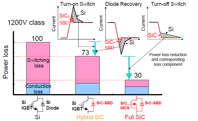
Figure 1: Evolution of SiC technology in power modules
Package outline and circuit diagram
The appearance of new 800A/1200V full SiC module (type name: FMF800DX-24A) and its internal circuit diagram are shown in Figure 2. The module contains 2 x 400A half bridge configurations. By externally paralleling the main P-, N- and AC-terminals an 800A/1200V 2in1 configuration is formed. By this paralleling approach the internal package inductance LS has been decreased to less than 10nH, which is important for limiting the overvoltage spikes at chip level due to high di/dt at switching of SiC-MOSFET.
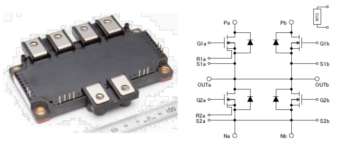
Figure 2: FMF800DX-24A package outline and internal circuit
The baseplate dimension of FMF800DX-24A is 62mm x 121mm. Thus the module size of new 800A/1200V full SiC module is about 1/2 compared with conventional Si-based IGBT modules having the same current rating, see Figure 3.
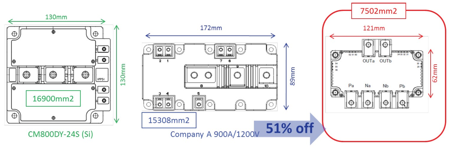
Figure 3: Footprint comparison
For monitoring the baseplate temperature TC a NTC-sensor located close to the MOSFET/FWDi chips is incorporated into the module. For short circuit and overcurrent protection MOSFET-chips with on-chip current sensing are used in one of the half bridge configurations (see Figure 2).
Main module parameters
The main parameters of 800A full SiC module are shown in Table 1.
The values of VDS, RDS(on) and VSD are given on chip level.
| Symbol | Parameter | FMF800DX-24A |
|---|---|---|
| VDSX | Drain-source voltage (at VGS=-15V) | 1200V (max) |
| ID | Drain current | 800A |
| ID(max) | Max. drain current (pulse) | 1600A |
| TJ(max) | Max. junction temperature | 150°C |
| VDS(on) | Drain-source On-voltage @ ID; TJ=150°C | 2,4V (typ) |
| RDS(on) | Drain-source On-resistance @ ID; TJ=150°C | 3,0mΩ (typ) |
| VSD | Source-drain voltage @ -ID; TJ=150°C | 2,2V (typ) |
| VGS(+) | Gate-source On-voltage | 13,5V…16,5V |
| VGS(-) | Gate-source Off-voltage | -9V…-16,5V |
| Rth(j-c)Q | MOSFET thermal resistance | 42 K/kW |
| Rth(j-c)D | FWDi thermal resistance | 61 K/kW |
Table 1: Main FMF800DX-24A parameters
Switching characteristics
Typical turn-on and turn-off switching waveforms at VCC=800V; TJ=150°C; RG(on)=RG(off)=5Ω are shown in Figure 4 and 5 for different drain currents ID=140A…1400A.
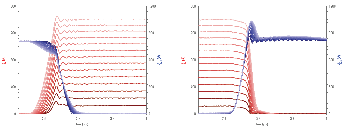
Figure 4: Turn-on waveforms / Figure 5: Turn-off waveforms
For limiting the turn-off overvoltage spike a cross-snubber capacitor of CS=6μF was connected between P- an N-terminals. The dependency of switching speed di/dt on drain current ID is shown in Figure 6 and 7 for different junction temperatures TJ=25°C; 75°C; 125°C; 150°C and different DC-link voltages VCC=600V; 800V.
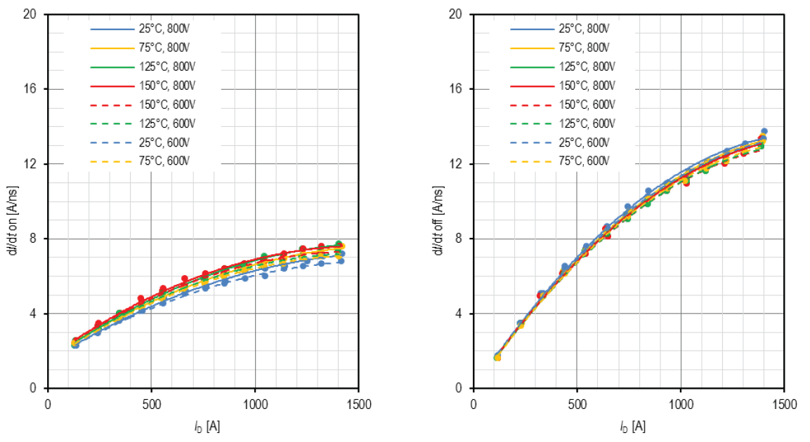
Figure 6: Turn-on di/dt versus ID / Figure 7: Turn-off di/dt versus ID
Two comments can be derived from Figure 6 and 7:
- The current slopes at turn–on and turn-off don’t show a strong dependency on chip temperature TJ and DC-link voltage VCC. This behavior differs from today’s IGBT-modules.
- The maximum di/dt at turning-off ID=1400A was about 13A/ns, which is quite similar to the switching speed known from today’s high current 1200V IGBT-modules.
Loss comparison with Si-based IGBT modules
The typical forward characteristics of new 800A full SiC module and existing 800A Si-based IGBT module are compared in Figure 8.
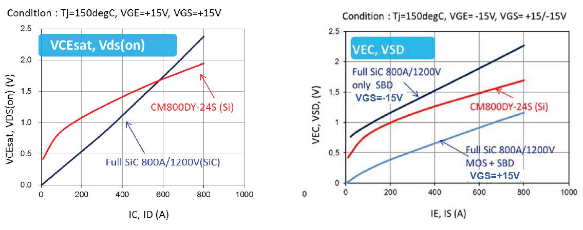
Figure 8: Forward characteristics
The comparison of switching energies in Figure 9 is indicating a key benefit of SiC technology: the switching losses can be drastically reduced compared with Si-based IGBT modules.
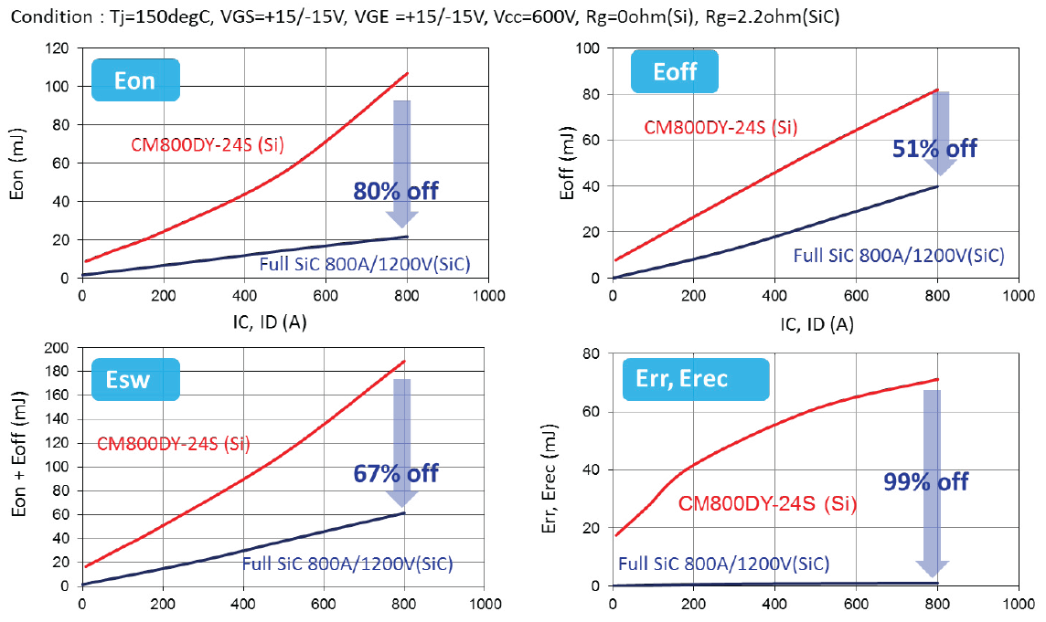
Figure 9: Switching energy comparison
This benefit can be seen in the power loss simulation results per Transistor/ FWDi-pair in inverter operation for two different PWM frequencies 15kHz and 30kHz and the corresponding temperature rise ΔT(j-c) in Figure 10 and Figure 11.
The total power loss can be drastically reduced (by 71% for 15kHz and 76% for 30kHz ) when full SiC-module is used. This loss reduction is mainly due to reduced switching loss. Conclusion: full SiC modules are very well suited for applications requiring high switching frequencies, where conventional Si-IGBT modules are reaching their thermal limit.
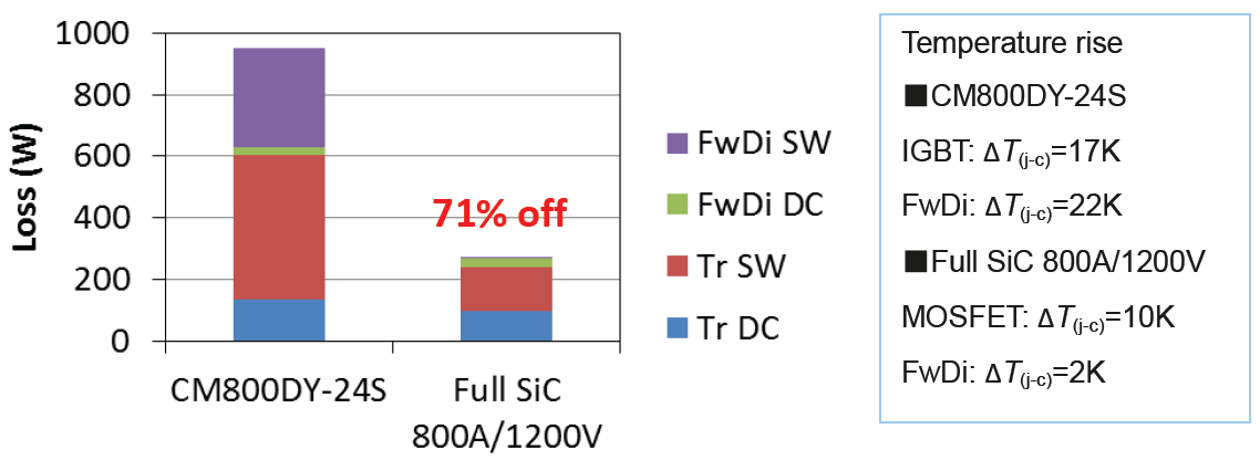
Figure 10: Loss and ΔT(j-c) simulation at fc=15kHz; VCC=600V; IO=400A(peak); PF=0,8; M=1,0
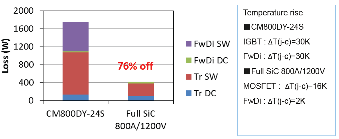
Figure 11: Loss and ΔT(j-c) simulation at fc=30kHz; VCC=600V; IO=400A(peak); PF=0,8; M=1,0
Gate Driver with SC-protection
The new 800A/1200V full SiC-Module can withstand a short circuit current for a limited time of tSC(max)=2,5μs. This limit is given in the SCSOA specification.
For conventional Si-IGBT modules typically a short circuit capability of tSC(max)=10μs is specified. In such conventional IGBT drivers a blanking time between desat-detection and SC-turn-off of typically to=1 3μs is installed, which is sufficient to ensure both: no false SC protection tripping and safe SC-turn-off.
Considering the relatively short tSC(max)=2,5μs specified for the new 800A/1200V full SiC-module another SC-protection method is proposed, known as RTC (Real Time Current Control). For this purpose one p-side and one n-side SiC MOSFET chip are equipped with a current sense electrode (refer to Figure 2). The equivalent circuit and the external view of this SiC MOSFET chip are shown in Figure 12.
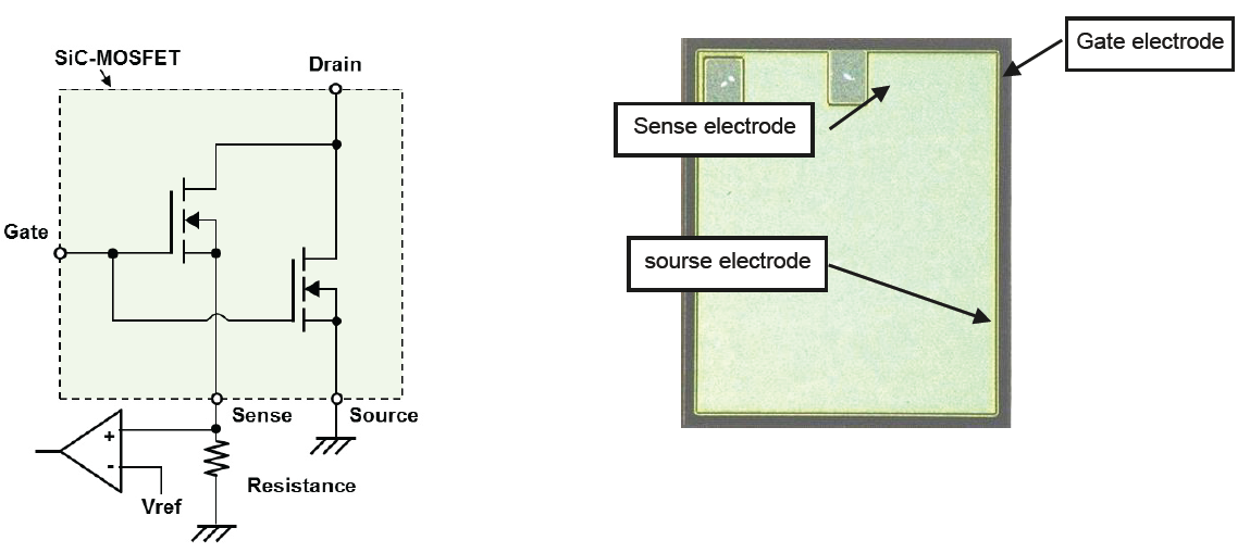
Figure 12: SiC MOSFET chip with current sense terminal
The functional block diagram of a dedicated gate driver for FMF800DX-24A using the proposed RTC protection is given in Figure 13. The measured short circuit waveforms during RTC operation are shown in Figure 14.
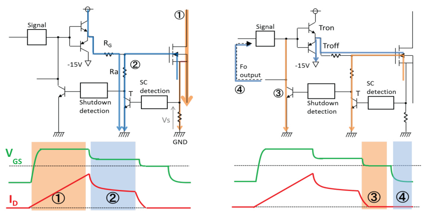
Figure 13: Principle of SC-protection by RTC
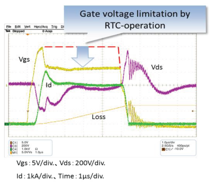
Figure 14: SC-waveforms during RTC-operation
During SC-turn-off operation by RTC four modes can be distinguished. In mode ① the main current ID is increasing until the voltage Vs across the shunt resistance is reaching a defined trip level. After reaching this trip level the mode ② starts: the transistor T is turned on and the Gate-Source voltage is reduced from +15V to about +7V resulting in a decreased SC-saturation current. Due to this SC-current reduction the allowable short circuit time is increased again to the well-known from IGBT drivers tsc(max)=10μs. Means from now on the conventional IGBT gate driver timing can be applied. During phase ③ the gate driver transistor Tron is switched off and VGS becomes Zero thus causing a soft turn-off of the short circuit current. In the final phase ④ the driver transistor Troff is turned on thus applying a negative VGS to the SiC MOSFET in off-state.
Summary and outlook
This paper is describing a new 800A/1200V full SiC dual module. Its type name is FMF800DX-24A. Compared with conventional Si-based IGBT modules the following unique points are confirmed:
- Module size reduced by 50%
- Switching loss (Esw=Eon + Eoff + Err) reduced by 75%
- Reliable SC-protection by RTC
Based on these features the new 800A/1200V full SiC module provides an interesting alternative to conventional IGBT modules in power electronic systems up to several 100kW, especially if one of the following system characteristics is of specific importance:
- Compact equipment size/high power density
- High efficiency
- High switching frequency (beyond the today’s limit reachable with IGBT modules)
References
[1]Press release No.2687 “Mitsubishi Electric to begin shipment of Silicon Carbide Power Modules Samples”, Tokyo, July 9, 2012
[2] Press release No.2733 “Mitsubishi Electric develops Large capacity SiC Power Module Technologies” Tokyo, February 14, 2013
Related posts
Now available – DC/DC converters from PREMIUM
We introduced a novelty to our permanent offer in DACPOL in the category of power supplies and converters and today...
Read more
New release in DACPOL lighting for lathes – Kira covers
We introduce a new product into the DACPOL category of industrial lighting and today we offer KIRA covers for...
Read more
Leave a comment