shopping_cart
Колица
0,00 PLN
0
цлипбоард
Морате бити пријављени да
-
-
-
Category
-
Полупроводници
- диоде
- Тиристори
-
Електро изоловани модули
- Електро изоловани модули | ВИСХАИ (ИР)
- Електро изоловани модули | ИНФИНЕОН (ЕУПЕЦ)
- Електро изоловани модули | Семикрон
- Електро изоловани модули | ПОВЕРЕКС
- Електро изоловани модули | ИКСИС
- Електро изоловани модули | ПОСЕИЦО
- Електро изоловани модули | АББ
- Електро изоловани модули | ТЕЦХСЕМ
- Go to the subcategory
- Мостовни исправљачи
-
Транзистори
- Транзистори | GeneSiC
- SiC MOSFET модули | Mitsubishi
- SiC MOSFET модули | STARPOWER
- АББ СиЦ МОСФЕТ модули
- IGBT модули | MITSUBISHI
- Транзисторски модули | MITSUBISHI
- MOSFET модули | MITSUBISHI
- Транзисторски модули | ABB
- ИГБТ модули | POWEREX
- ИГБТ модули | ИНФИНЕОН (ЕУПЕЦ)
- Silicijum-karbidni poluprovodnički elementi
- Go to the subcategory
- Гате Дриверс
- Блокови напајања
- Go to the subcategory
- Električni pretvarači
-
Пасивне компоненте (кондензатори, отпорници, осигурачи, филтери)
- Otpornici
-
Osigurači
- Minijaturni osigurači za elektronske sisteme serije ABC i AGC
- Cilindrični brzi osigurači
- Osigurači sa odloženim delovanjem GL/GG i AM karakteristika
- Ultra-brzi osigurači
- Brzi osigurači sa britanskim i američkim standardom
- Brzi osigurači sa evropskim standardom
- Vučni osigurači
- Visokonaponski osigurači
- Go to the subcategory
-
Kondenzatori
- Motorni kondenzatori
- Elektrolitski kondenzatori
- Kondenzatori - snubberi
- Energetski kondenzatori
- Kondenzatori za DC kola
- kondenzatori za kompenzaciju snage
- Visokonaponski kondenzatori
- Kondenzatori za indukciono grejanje
- Impulsni kondenzatori
- ДЦ ЛИНК кондензатори
- Кондензатори за АЦ/ДЦ кола
- Go to the subcategory
- EMI filtri
- Superkondenzatori
- Заштита од пренапона
- TEMPEST филтери за откривање емисије
- Одводник пренапона
- Go to the subcategory
-
Releji i kontaktori
- Теорија релеја и склопника
- Trofazni poluprovodnički releji
- Трофазни полупроводнички релеји наизменичне струје
- Регулатори, команде и додаци
- Sistemi za meki sart i reverziblni kontaktori
- Elektromehanički releji
- Kontaktori
- Rotacioni prekidači
-
Једнофазни полупроводнички релеји наизменичне струје
- Једнофазни релеји наизменичне струје, 1 серија | Д2425 | Д2450
- Jednofazni poluvodički izmjenični releji CWA i CWD serije
- Jednofazni poluvodički izmjenični releji CMRA i CMRD serije
- Jednofazni poluvodički izmjenični releji - serija PS
- Двоструки и четвороструки полупроводнички релеји наизменичне струје, серије Д24 Д, ТД24 К, Х12Д48 Д.
- Jednofazni poluvodički releji - gn serije
- Jednofazni kružni releji Ckr serije
- Jednofazni AC poluvodički releji za DIN sabirnice - ERDA I ERAA serija
- 150A AC jednofazni releji
- Čvrsti releji s ugrađenim hladnjakom na šini - ENDA, ERDA1 / ERAA1 series
- Go to the subcategory
- Monofazni poluprovodnički releji za štampane ploče
- Интерфејс релеји
- Go to the subcategory
- Indukcione komponenete
- Radijatori, Varistori, Termička zaštita
- Ventilatori
- Klimatizacija, Pribor za industrijska kućišta, Kuleri
-
Батерије, пуњачи, бафер напајања и претварачи
- Батерије, пуњачи - теоријски опис
- Litijum-jonske baterije. Nestandardne baterije. Sistem za upravljanje baterijom (BMS)
- Baterije
- Punjači i dodaci za baterije
- UPS i puferski izvori napajanja
- Pretvarači i dodaci- fotonaponski
- Складиште енергије
- Гориве ћелије
- Литијум-јонске батерије
- Go to the subcategory
- Automatika
-
Kablovi, Licnaste žice, Kablovski kanali, Fleksibilne veze
- жице
- Кабловски уводи и спојнице
- лицнастим жице
- Каблови за специјалне намене
- схиртс
-
плетенице
- браидс флат
- плетенице коло
- Врло флексибилан плетеница - стан
- Врло флексибилан плетеница - коло
- Бакар плетена цилиндрични
- Бакра плетеница штит и цилиндрични
- Флексибилни уземљење траке
- Плетенице ЦИЛИНДРИЦАЛ поцинковани и нерђајућег челика
- ПВЦ изолацијом бакарне плетенице - Температура 85 ° Ц
- Стан плетени алуминијум
- Цоннецтион Кит - плетенице и цеви
- Go to the subcategory
- Прибор за вучу
- папучица
- Флексибилни исолатед сабирнице
- Вишеслојна флексибилан шина
- системи за управљање кабл
- Go to the subcategory
- View all categories
-
Полупроводници
-
-


7th Generation NX type (NX7) Converter Inverter Brake (CIB) Modules
 Converter Inverter Brake (CIB) Modules")
7th Generation NX type (NX7) Converter Inverter Brake (CIB) Modules
Developed to address the requirements of high performance drives by utilizing an innovative packaging concept and an advanced chip technology.
Applications such as elevator drives or servomotors have several special requirements. One on hand, high efficiency is important, while on the other hand, the inverter unit be resilient to the different types of load cycling. Furthermore, the inverter must be designed as compact as possible. NX7 CIB modules aim to address these challenges.
By Toshinari Hirai and Narender Lakshmanan, Mitsubishi Electric Europe B.V
Advanced Chip Technology Combined with a New Packaging Concept:
Each CIB module consists of an integrated 3 phase inverter part, a converter (3 ph diode rectifier) part and a brake chopper part. The line-up of the latest NX7 CIB modules is shown in Figure 1. The NX7 CIB modules utilize the latest 7th generation CSTBT™ IGBT along with the RFC (Relaxed Field of Cathode) diodes. The electrical characteristics of the new thin wafer 7th generation chips have been tuned for the reduction of overall power losses.
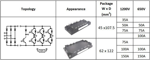
Figure 1: Line-up of the NX7 CIB Modules. NOTE: Pressfit and PCTIM options available.
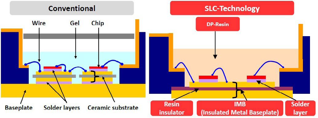
Figure 2: Cross section of the NX7 package versus a conventional module package.
The NX7 CIB employs a new packaging concept – the SLC (SoLid Cover) Technology which includes an insulated metal baseplate structure (refer to Figure 2). The conventional baseplate has been replaced by an insulated metal baseplate structure where the metal baseplate contains an organic insulation layer directly bonded to it. Therefore the conventional substrate solder between metal baseplate and isolation ceramic has been eliminated. The soft silicone gel of the conventional structure is replaced by the hard DP-resin (direct potting resin) [1].
Minimizing Losses and Maximizing Performance:
Operating the inverter at elevated switching frequencies helps in reducing the audible noise, hence low loss operation even at high switching frequencies is an important capability for applications such as elevators. In addition, limiting the IGBT chip temperature rise during low rotation speed (low output frequency) operation is a key requirement.
Figure 3 indicates the overall power loss comparison of an NX7 CIB module (CM50MXUA-24T) with a previous 6th gen. IGBT module (CM50MXA-24S) considering different switching frequencies and a low output current frequency of fout=5Hz. The benefit in terms of pow-
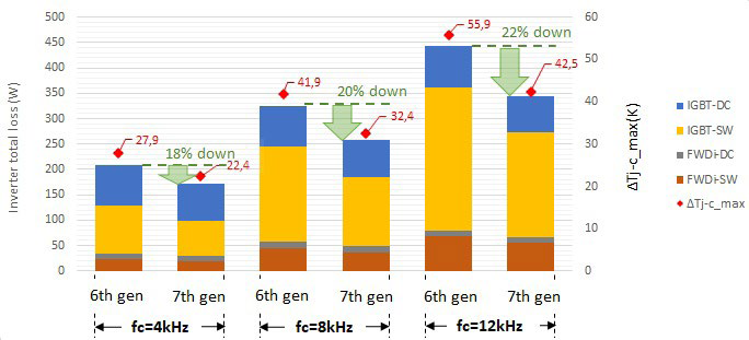
Figure 3: Power loss and junction temperature performance of the NX7 CIB vs conventional module. Conditions: VCC = 600V, Io = 24 Arms, PF = 0.9, M = 1, fout = 5 Hz, Data @ Tj = 125°C.W
er loss between a conventional module and an NX7 CIB module increases with increase in switching frequency. This can be attributed to the optimization in the trade-off between the switching losses and the ON state losses in the new 7th generation chip technology. A combination of loss reduction and the low thermal resistance (chip to case) offered by the 7th generation chip technology ensures that the maximum junction temperature can be reduced by utilizing the NX7 CIB module. The analysis indicated in Figure 3 has been carried out considering a target switching dv⁄dt (max)= 10 kV/μs.
Designed for High Reliability:
Intermittent operation is a characteristic feature of applications such as elevators. The impact of load cycling can be categorized into two types of cycling phenomena: power cycling and thermal cycling. Power cycling refers to a cycling of the junction temperature which affects the reliability of the chip-tobond wire contact whereas thermal cycling refers to the cycling of baseplate temperature which conventionally affect the solder layer connecting the isolation substrate and the baseplate. But due to the elimination of the ceramic substrate and the solder layer, the limitation pertaining to thermal cycling is not present in NX7 CIB modules.
Case 1: Extended Loading Conditions (temperature swing at the heatsink and case):
It is common for applications such as elevators to experience operation cycles where the heatsink temperature rises to an allowable point and then falls back to the ambient temperature. Session involving continuous operation which would generate a temperature swing at the heatsink, would also involve temperature swings at the case of the power module and at the chip surface (junction). An example of such operation is represented in Figure 4. For this analysis, the Mitsubishi Electric 6th generation modules represent the conventional modules.
The following points are the key conclusions from Figure 4:
- Bottleneck identification: For conventional modules which utilize a baseplate solder layer, thermal cycling performance is the lifetime limitation factor for long operation cycles due to the degradation of the solder layer under such conditions.
- Solution: The bottleneck (solder layer) has been eliminated in the new NX7 module due to the adoption of the IMB structure.
Case 2: Short term loading conditions (temperature swing predominantly at the chip):
Operating cycles (in the range of a few seconds) which generate temperature swings only at IGBT chip (ΔTj) affect the reliability of the chip to bond wire contact. The amplitude of the ΔTj is the deciding factor with regards to the power cycling lifetime. This point has been addressed by employing the low loss 7th generation chip technology
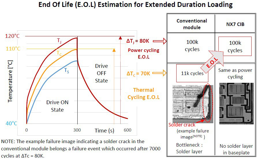
Figure 4: Lifetime estimation for extended duration loading (Conventional module vs NX7 CIB).
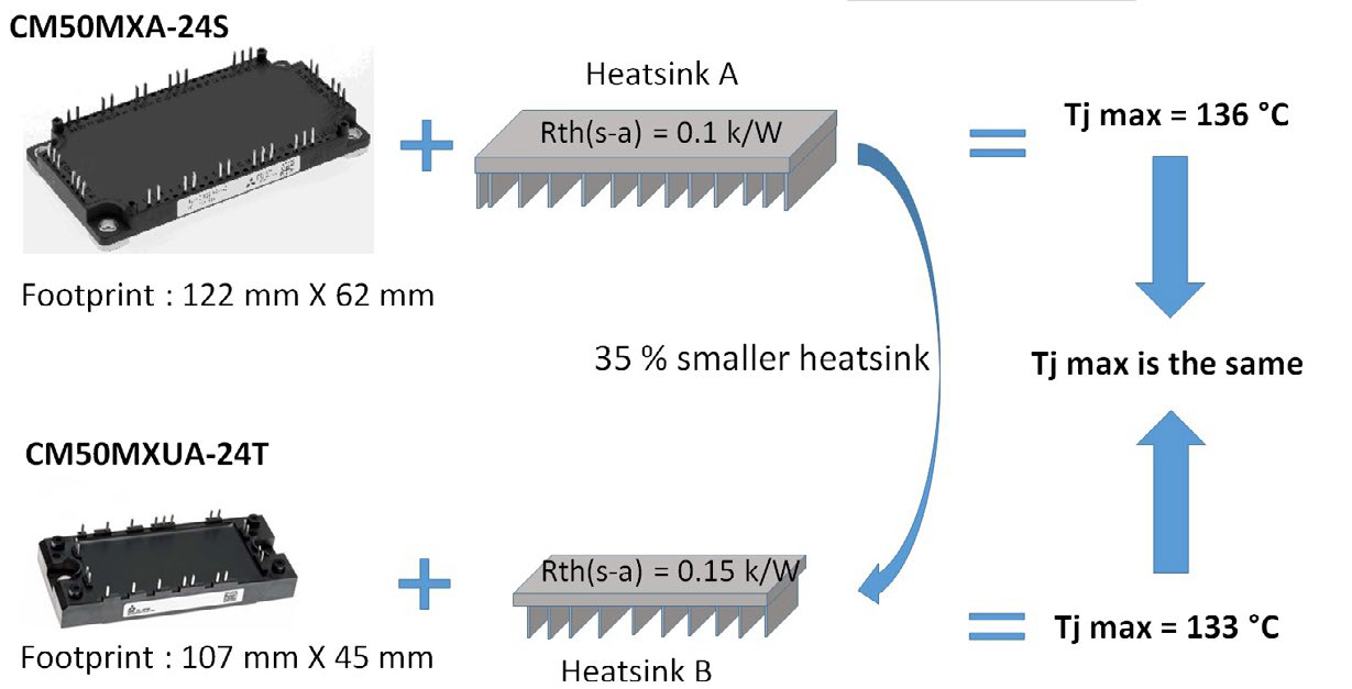
Figure 5: Compactness by heatsink reduction. Conditions: Vcc = 600V, fc = 12 kHz, fout = 5 Hz, M = 1, PF = 0.9, Ic = 24 Arms, Ta = 30 °C, data @ Tj = 125 °C
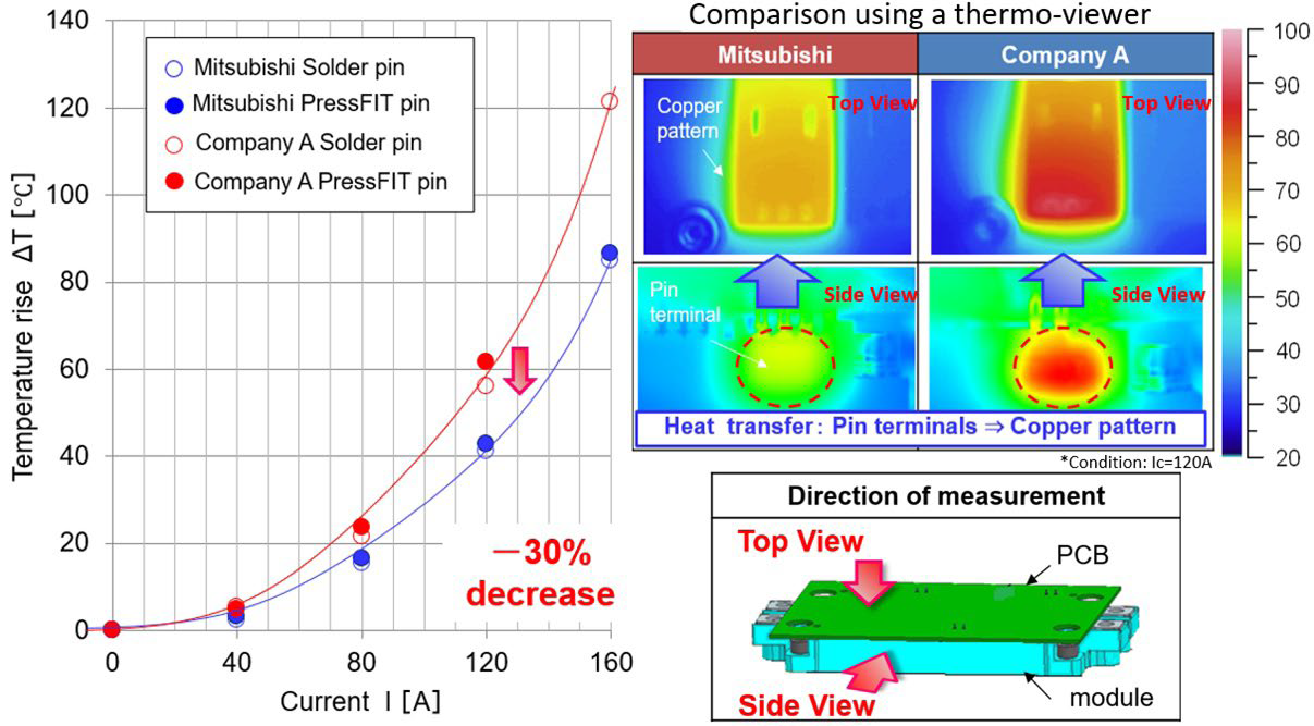
Figure 6: Optimization of terminal temperature in the NX7 CIB module.
in combination with the optimized chip to case thermal resistance in the NX7 module. This combination ensures that for the same operating condition, the corresponding ΔTj is lower (compared the performance of the conventional module). This tendency can be understood from the following results indicating power cycling capability based on the conditions mentioned in Figure 3 (for fc = 12 kHz):
- Conventional CIB (CM50MXA-24S): ΔTj = 54.52 K: 600 thousand cycles (approx.)
- NX7 CIB (CM50MXUA-24T): ΔTj = 36.64 K:WWWW 6 million cycles (approx.)
Summary – Overall lifetime enhancement
Overall improvement in lifetime has been ensured by the following two-step strategy:
- Elimination of the thermal cycling bottleneck
- Reduction of ΔTj to achieve better power cycling capability
Compact Design:
To achieve a compact design, several important considerations have to be made. The following points illustrate the advantage offered by adopting an NX7 CIB module.
1. Since the NX7 CIB module exhibits an improved loss performance and superior thermal performance (refer Figure 4), the designer can shrink the size of the heatsink in order to achieve an overall compact design. The example presented in Figure 5 illustrates a 35% reduction of the heatsink without causing an increase in the maximum junction temperature.
2. To achieve compactness, the classical copper busbar structure can be replaced by a PCB which would be connected to the terminals of the power module via pressfit or soldering. The challenge with this approach is that, due to high current density at the terminal pins, the temperature developed at the terminal could impose a limitation on the maximum operating current. This possibility has been taken into consideration while developing the NX7 CIB and accordingly the pin structure has been designed to reduce the temperature developed at the terminal during operation. As indicated in Figure 6, the temperature rise developed at the terminals of the Mitsubishi module (NX7 CIB) is lower in comparison with a competitor’s design. The improved thermal conductivity of the potting material (DP-resin) versus gel is an added advantage.
Scalable solutions:
The NX7 CIB line-up allows the designer to develop platform solutions – one mechanical design for multiple power ratings. For example, (refer Figure 1), in the 1200V category, the 45mm x 107.5mm module is available in 3 different current ratings (35A, 50A and 75A and the 62mm x 122mm module is available in 3 different current ratings (75A, 100A, 150A). This allows the designer to develop one mechanical design for 3 different power levels.
Conclusion:
The requirements of applications such as elevator drives have been taken into consideration while developing the NX7 CIB module. The unique combination of the SLC technology packing and the 7th generation chip technology allows the designer to develop an efficient, reliable and a compact inverter that can be used as a platform solution for multiple power levels.
References:
[1] Thomas Radke, et al: Enhanced IGBT Module Power Density Utilizing the Improved Thermal Conductivity of SLCTechnology, Bodo’s Power systems, June 2016
[2] Thomas Radke, et al : New Horizons in Thermal Cycling Capability Realized with the 7th gen. IGBT module Based on SLC-Technology, Bodo’s Power systems, May 2017
[3] MELCOSIM: IGBT thermal and loss simulation software, available at www. mitsubishielectric.com/semiconductors/ simulator/
Related posts
Now available – DC/DC converters from PREMIUM
We introduced a novelty to our permanent offer in DACPOL in the category of power supplies and converters and today...
Read more
New release in DACPOL lighting for lathes – Kira covers
We introduce a new product into the DACPOL category of industrial lighting and today we offer KIRA covers for...
Read more
Leave a comment