
Ви повинні увійти в систему
Category


Фотографії призначені тільки для інформаційних цілей. Подивитися специфікацію продукту
please use latin characters
Description
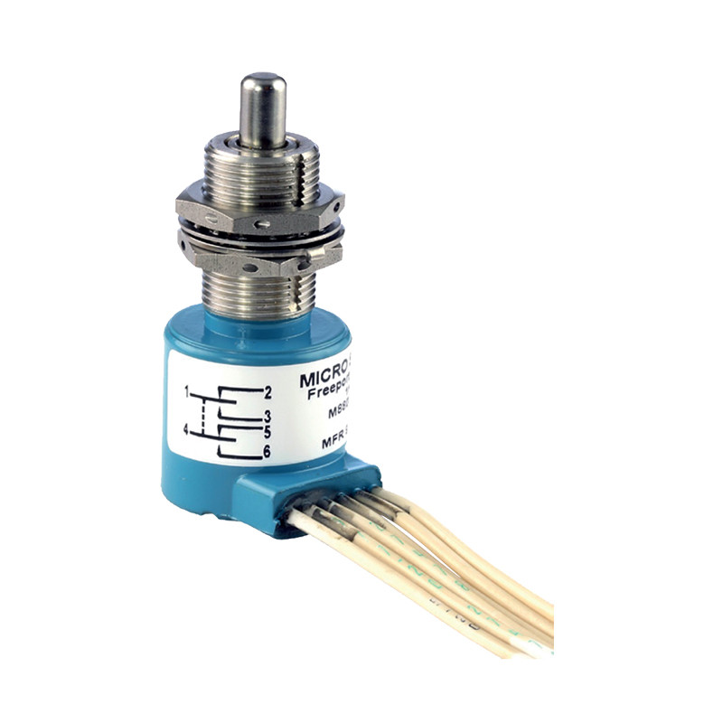
The Honeywell MICRO SWITCH™ Series of EN limit switches are bushing mount designed, manufactured, and qualified to MIL-PRF-8805 standards. These products provide a durable switch for commercial and military aircraft as well as commercial and military ground-based equipment. Other applications include off-road equipment where severe environments are encountered.
The EN Series of switches have proven to deliver consistent and reliable operation in harsh environments on critical applications for more than 65 years.
EN limit switches features
Examples of applications
Tecjnical data
| Characteristics | Parameter |
| Description | Environmentally sealed military qualified limit switch series (MIL-PRF-8805) |
| Housing and bushing material | 300 Series stainless steel |
| Contact material | Silver alloy, gold plated, gold bifurcated |
| Mechanical endurance | 25.000 cycles/min |
| Electrical endurance | 25.000 cycles/min @ rated load |
| Circuitry | 1PST (one-pole single throw) to 6PDT (six-pole double throw) |
| Electrical rating | Up to 15 A @ 28 V DC |
| Dielectric strength (initial) | 1000 V RMS; 500 μA max. leakage |
| Insulation resistance (initial) | 500 V DS; 1000 MΩ/min |
| Environmental sealing | Symbol 4, resilient seal per MIL-PRF-8805 |
| Operating temperature range | -54 °C up to 125 °C (-65 °F up to 257 °F) |
| Shock | Symbol M (100 g) per MIL-PRF-8805 |
| Vibration | Symbol 1 (10 g peak), 10 - 500 Hz |
| Standards | Design conforms to MIL-PRF-8805 |
Example of switch design

Diagram

Ви зацікавлені у цьому продукті? Вам потрібна додаткова інформація або індивідуальні розцінки?
Ви повинні увійти в систему
Description
The Honeywell MICRO SWITCH™ Series of EN limit switches are bushing mount designed, manufactured, and qualified to MIL-PRF-8805 standards. These products provide a durable switch for commercial and military aircraft as well as commercial and military ground-based equipment. Other applications include off-road equipment where severe environments are encountered.
The EN Series of switches have proven to deliver consistent and reliable operation in harsh environments on critical applications for more than 65 years.
EN limit switches features
Examples of applications
Tecjnical data
| Characteristics | Parameter |
| Description | Environmentally sealed military qualified limit switch series (MIL-PRF-8805) |
| Housing and bushing material | 300 Series stainless steel |
| Contact material | Silver alloy, gold plated, gold bifurcated |
| Mechanical endurance | 25.000 cycles/min |
| Electrical endurance | 25.000 cycles/min @ rated load |
| Circuitry | 1PST (one-pole single throw) to 6PDT (six-pole double throw) |
| Electrical rating | Up to 15 A @ 28 V DC |
| Dielectric strength (initial) | 1000 V RMS; 500 μA max. leakage |
| Insulation resistance (initial) | 500 V DS; 1000 MΩ/min |
| Environmental sealing | Symbol 4, resilient seal per MIL-PRF-8805 |
| Operating temperature range | -54 °C up to 125 °C (-65 °F up to 257 °F) |
| Shock | Symbol M (100 g) per MIL-PRF-8805 |
| Vibration | Symbol 1 (10 g peak), 10 - 500 Hz |
| Standards | Design conforms to MIL-PRF-8805 |
Example of switch design

Diagram

Вашу оцінку відгуку не було надіслано
Поскаржитись на відгук
Скаргу надіслано
Ваш відгук не надіслано
Написати свій відгук
Відгук надіслано
Ваш відгук не надіслано
